
 Online Shop
 English
 China - 简体中文
 Global - English
 Brazil - Português
 Netherlands - Dutch
 Italy - Italiano
 Germany - Deutsch
 Spain - Español
 France - Français
 Vietnam - Tiếng Việt
 Poland - Polski
 Australia - English
 Japan - 日本語
Zhuo Yiran — Senior After-Sales Service Engineer, Energy Storage Systems

Scalable 100kW–2.5MW Commercial and Industrial Energy Storage Solution
Commercial and industrial energy users increasingly require more than basic battery backup. They need a complete energy platform that can reduce peak demand, improve renewable-energy utilization, protect critical loads, support backup operation, and adapt to changing electricity tariffs. The 100kW–2.5MW C&I ESS Solution is designed to meet these requirements through a modular architecture combining power conversion, photovoltaic input management, static transfer switching, battery storage, and energy management.
Built around 100kW and 125kW power conversion system modules, 200kW MPPT modules, 500kW static transfer switch modules, and BOS-B Pro-A3 battery systems, the solution can be configured for projects ranging from smaller commercial facilities to large industrial sites. Its modular structure enables system capacity to grow as energy demand, renewable generation, or backup requirements increase.
Instead of forcing every project into one fixed cabinet configuration, the solution provides a flexible platform that can be sized according to load capacity, battery duration, photovoltaic capacity, grid conditions, and operating objectives. This approach is particularly valuable for factories, logistics centers, office campuses, retail facilities, data-related infrastructure, agricultural operations, and other sites where energy costs and power continuity directly affect business performance.
The system supports on-grid operation, off-grid operation, generator integration, and rapid transfer between operating modes. With a static transfer switch switching time of less than 10 milliseconds, it is engineered to maintain continuity for sensitive and critical loads. In off-grid mode, the power conversion system can support twice its peak power output for up to 12 seconds, helping the system manage demanding startup currents and short-duration overloads.
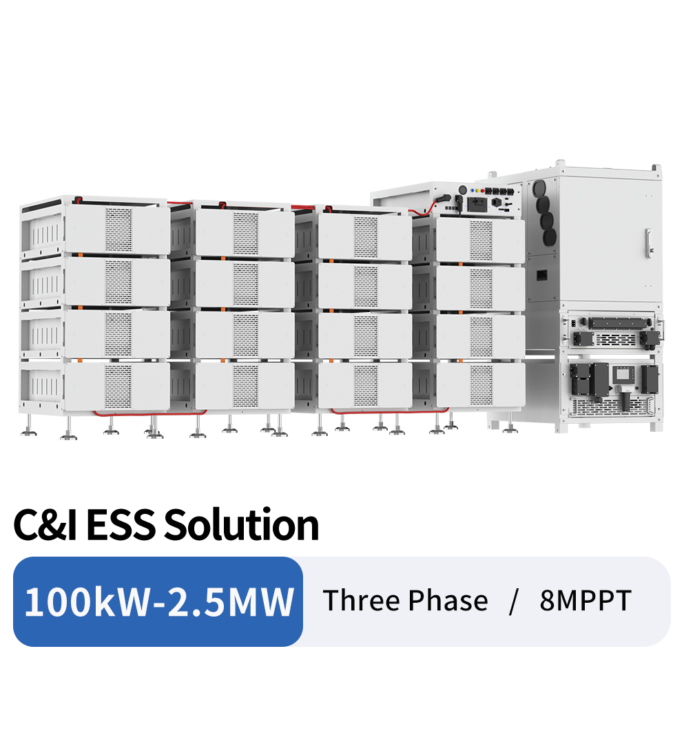
100kW-2.5MW C&I ESS Solution
Meeting the Changing Requirements of C&I Energy Systems
Commercial and industrial facilities often have complex electrical profiles. A factory may experience high demand during production shifts, while solar generation is strongest at another time of day. A warehouse may require substantial cooling or refrigeration loads. An office building may need reliable power for elevators, servers, security systems, and communication equipment. In each case, a battery energy storage system must perform more functions than simple energy shifting.
A modern C&I ESS must respond quickly to grid interruptions, coordinate with photovoltaic generation, work with backup generators, manage battery charging and discharging, and provide clear operating information to facility managers. It must also be capable of expansion without requiring a complete redesign of the original installation.
The 100kW–2.5MW solution addresses these needs with four main design principles:
First, power conversion is modular. A site can use 100kW or 125kW PCS units individually or combine multiple units to reach a significantly higher system capacity.
Second, photovoltaic input is independently managed through dedicated MPPT modules. Each MPPT module includes eight trackers and supports up to 40A per tracker, enabling more flexible PV string allocation and improved management of different roof orientations, array sections, and module characteristics.
Third, backup transfer is handled by a dedicated 500kW STS module. This separates high-speed load transfer from the battery inverter function and allows the system to coordinate grid, PCS, generator, and load-side operation in an organized architecture.
Fourth, energy storage is based on a scalable battery platform. Each BOS-B Pro-A3 battery system provides up to 257.23kWh of nominal energy, with up to 231.51kWh of usable energy at the specified operating conditions. Battery clusters can be combined according to the required storage duration and power profile.
Modular Architecture for Project-Specific Design
The modular concept is one of the solution’s most important advantages. Conventional C&I energy storage products are often offered as fixed-capacity systems. Although fixed systems can simplify selection for standardized applications, they may create limitations when a project has unusual power, storage, or expansion requirements.
A modular system allows the EPC contractor, system integrator, or facility owner to choose the number of power conversion modules, MPPT modules, STS modules, and battery clusters according to the project’s actual needs. This reduces the risk of significant oversizing at the beginning of a project and allows future capacity additions to be planned from the outset.
The PCS platform includes 100kW and 125kW models. Multiple PCS units can be combined to support system scalability up to 2.5MW. This capacity range makes the product suitable for medium-sized commercial sites as well as larger industrial energy systems.
Modular expansion can also improve serviceability. If a single power conversion module requires inspection or replacement, maintenance can be performed at the module level rather than requiring the entire system to be taken offline. The exact maintenance procedure depends on site design, operating conditions, and applicable safety procedures, but the underlying architecture supports more targeted servicing than a single large integrated converter.
Standardized modules can also simplify project engineering. Electrical designers can work with repeatable power blocks, while installers can develop consistent cable, protection, and communications arrangements across multiple sites. For organizations managing a portfolio of facilities, this repeatability can reduce design variation and support more consistent commissioning and training.
Typical Modular Configuration
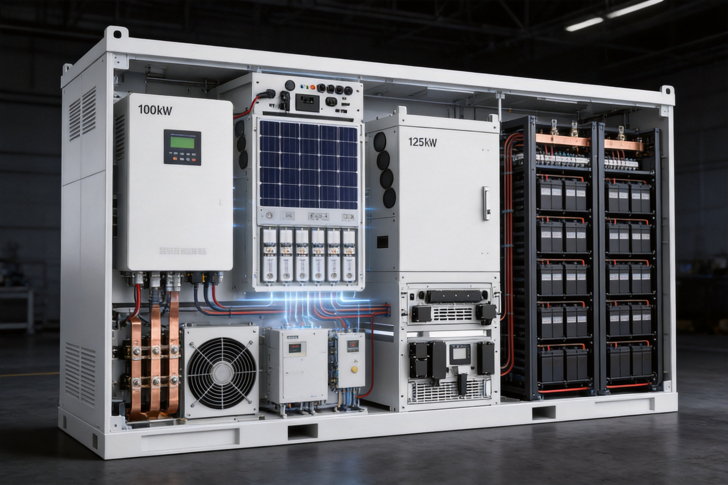
A standard configuration may include a 100kW or 125kW PCS module, one or more 200kW MPPT modules, a 500kW STS module, and one or more BOS-B Pro-A3 battery systems. The number of modules depends on the required AC power, photovoltaic input, battery energy, backup load, and generator interface.
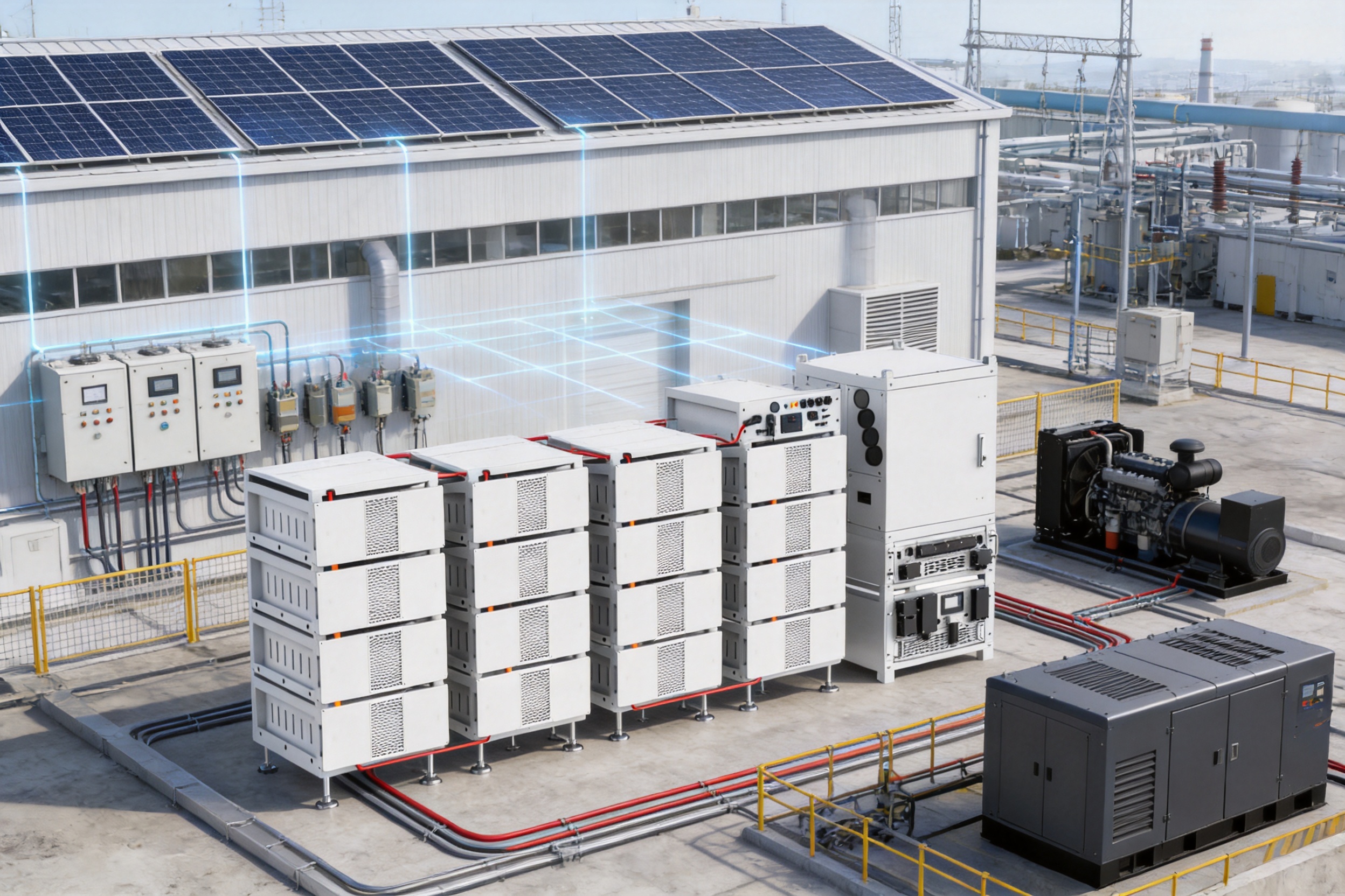
The architecture also supports high-power paths for diesel generators, loads, and grid connections. The STS module is rated for 500kW active power and supports grid-side, load-side, and generator-side connections. This provides a practical foundation for facilities that require generator coordination or islanded operation.
| System Element | Available Specification | Primary Function |
|---|---|---|
| PCS module | 100kW or 125kW | Battery charging, discharging, and AC power conversion |
| MPPT module | 200kW maximum PV access power | Photovoltaic input management and maximum power tracking |
| STS module | 500kW | Rapid transfer among grid, off-grid, and generator operating modes |
| Battery system | Up to 257.23kWh nominal energy per system | Energy storage and backup power support |
| System scalability | Up to 2.5MW | Expansion for larger commercial and industrial applications |
High-Speed Backup with UPS-Level Switching
Power interruptions can cause substantial losses in industrial and commercial facilities. Production equipment may stop, control systems may reset, network equipment may disconnect, and sensitive processes may be interrupted. Even short outages can create costs that are disproportionate to the duration of the event.
The integrated SUN-STS500L static transfer switch is designed to address this challenge. Its specified off-grid switching time is less than 10 milliseconds. This rapid transition helps maintain power continuity when the grid fails or when the system intentionally changes from on-grid to off-grid operation.
The STS module supports switching among on-grid, off-grid, and diesel operating modes. This gives the system greater operational flexibility than a battery inverter that only provides grid-following backup. A facility can combine grid power, battery storage, photovoltaic generation, and generator power in a coordinated energy architecture.
Rapid switching is particularly useful for critical loads such as control systems, communications equipment, security infrastructure, medical support equipment, refrigeration systems, and industrial automation. Actual compatibility with a specific load depends on the load’s power quality requirements, inrush current, protection settings, and local electrical design. Nevertheless, the less-than-10-millisecond transfer specification provides a strong foundation for UPS-level backup applications.
The 500kW STS rating also allows high-power loads to be supported through a single transfer architecture. The module includes grid and PCS connections, a load-side connection, and a generator-side connection. Its three-phase voltage options include 220/380V and 230/400V, with 50Hz or 60Hz operating frequencies.
Strong Overload Capability for Demanding Loads
Many commercial and industrial loads do not behave like constant resistive loads. Motors, pumps, compressors, transformers, and other equipment may draw high current during startup. If the energy storage system cannot handle short-term overloads, unnecessary trips may occur even when the average load is within the system’s continuous rating.
In off-grid mode, the PCS supports twice its peak power output for up to 12 seconds. This overload capability helps the system manage short-duration peaks associated with motor starting, equipment energization, and transient load changes.
For example, a site with a 125kW PCS may have brief load events that exceed the continuous rating. The short-term overload function can provide additional operating headroom while the system stabilizes the load profile. The suitability of the system for a particular motor or transformer must still be evaluated using the equipment’s starting current, power factor, harmonics, and protection requirements.
This capability is an important distinction between a storage solution designed for real industrial conditions and one designed only for steady laboratory loads. Facilities can use the system for a broader range of applications without relying exclusively on extensive load shedding or oversized equipment.
Dedicated MPPT Design for Flexible Solar Integration
Photovoltaic arrays installed on commercial and industrial buildings are rarely perfectly uniform. Roof sections may face different directions, have different tilt angles, or experience different shading conditions. Ground-mounted arrays may use multiple blocks with different cable lengths and environmental exposure. A single tracker may not be able to operate all sections at their optimum voltage and current.
The 200kW MPPT module uses eight independent maximum power point trackers. Each tracker supports up to 40A of operating current and up to 60A of short-circuit current. This design gives system engineers more flexibility when allocating PV strings to the inverter input.
Independent tracking can help reduce the impact of mismatch between different array sections. When one section is shaded or oriented differently, it does not necessarily force all other sections to operate away from their preferred operating point. The result can be better utilization of available PV generation across complex commercial roofs and industrial sites.
The MPPT module supports a maximum PV access power of 200kW and a maximum PV input power of 160kW according to the listed specifications. Its maximum PV input voltage is 800V, with an MPPT voltage range of 180V to 750V and a full-load MPPT voltage range of 450V to 750V.
The maximum operating PV input current is specified as eight channels of 40A, while the maximum input short-circuit current is specified as eight channels of 60A. The module’s maximum efficiency is greater than 99%, and its MPPT efficiency is greater than 99.9%.
| MPPT Parameter | Specification |
|---|---|
| Model | SUN-MPPT-L01-EU-AM8 |
| Maximum PV access power | 200kW |
| Maximum PV input power | 160kW |
| Maximum PV input voltage | 800V |
| MPPT voltage range | 180–750V |
| Full-load MPPT voltage range | 450–750V |
| Number of MPPT trackers | 8 |
| Maximum operating current per tracker | 40A |
| Maximum short-circuit current per tracker | 60A |
| Maximum efficiency | Greater than 99% |
| MPPT efficiency | Greater than 99.9% |
Battery Storage with High Usable Energy
The BOS-B Pro-A3 battery system is based on lithium-ion technology and is designed for modular commercial and industrial storage. Each battery module has a nominal energy of 16.08kWh, a nominal voltage of 51.2V, and a capacity of 314Ah. Between five and sixteen battery modules can be connected in series, depending on the selected configuration and application.
At the maximum specified configuration, the battery system reaches 257.23kWh of nominal energy and 231.51kWh of usable energy. The recommended depth of discharge is 90%. This balance between energy availability and operating reserve supports practical daily cycling while preserving a controlled operating window for the battery system.
The battery platform can be matched with PCS units according to whether the installation is on-grid or off-grid. The listed matching guidance specifies 14 to 16 battery units for PCS on-grid applications and 15 to 16 units for PCS off-grid applications. For PCS plus MPPT configurations, the recommended number of units depends on the MPPT open-circuit voltage.
This matching flexibility allows system designers to consider both the DC voltage requirements of the PCS and the open-circuit voltage characteristics of the PV array. Proper configuration is essential for safe and efficient operation, particularly in locations with low ambient temperatures where PV open-circuit voltage can rise.
The battery system includes communication through TCP, RS485, and CAN interfaces, with CAN communication used for battery management system coordination. Its battery management strategy supports communication between the battery system and power conversion equipment so that charging and discharging behavior can respond to battery conditions.
The battery system is specified for charging from 0°C to 55°C and discharging from -20°C to 55°C. Thermal management uses smart fan cooling. The battery enclosure has an IP20 rating and is intended for rack-mounted installation. Installation conditions, ventilation, fire protection, and environmental controls must follow the applicable project design and local regulations.
Battery Safety and Lifecycle Design
Battery safety is addressed through a combination of lithium iron phosphate battery technology and integrated module-level aerosol fire suppression. LiFePO4 chemistry is widely used in stationary storage because of its thermal stability and suitability for repeated cycling. The module-level suppression approach adds an additional safety layer intended to respond close to the source of a potential thermal event.
The listed cycle-life condition is 6,000 or more cycles to an end-of-life capacity threshold of 70%, based on 25°C and a 0.5C charge and discharge condition. Real-world results vary according to operating temperature, depth of discharge, charging strategy, installation quality, maintenance, and duty cycle.
The battery system carries a stated 10-year warranty period. Warranty terms remain subject to the final installation site, operating profile, commissioning conditions, and the applicable warranty policy.
PCS Performance for Commercial Energy Management
The PCS modules provide bidirectional conversion between the battery DC bus and the AC electrical system. The 100kW model has a rated AC input/output active power of 100kW, while the 125kW model has a rated active power of 125kW. Their maximum apparent power ratings are 110kVA and 125kVA respectively.
The battery voltage range is 630V to 1000V. The maximum charging and discharging current is 175A for the 100kW model and 200A for the 125kW model. The PCS uses a self-adaptive charging strategy for lithium-ion batteries through coordination with the BMS.
The AC input and output voltage options include 220/380V and 230/400V, with a voltage range of 0.85Un to 1.1Un. The grid connection form is 3L+N+PE. The system supports both 50Hz and 60Hz operation within the specified frequency ranges.
Power factor adjustment ranges from -1 to 1, enabling the system to support active and reactive power management according to project requirements and grid regulations. Total current harmonic distortion is specified at less than 3% of nominal power, while DC injection current is specified at less than 0.5% of rated current.
| PCS Parameter | 100kW Model | 125kW Model |
|---|---|---|
| Model | SUN-100K-PCS01HP3 | SUN-125K-PCS01HP3 |
| Rated active power | 100kW | 125kW |
| Maximum apparent power | 110kVA | 125kVA |
| Battery voltage range | 630–1000V | 630–1000V |
| Maximum charging current | 175A | 200A |
| Maximum discharging current | 175A | 200A |
| Maximum efficiency | 98.5% | 98.5% |
| Euro efficiency | 97.8% | 97.8% |
| Power factor range | -1 to 1 | -1 to 1 |
| Communication interfaces | Wi-Fi, RS485, CAN, meter | Wi-Fi, RS485, CAN, meter |
Integrated EMS for Multiple Operating Objectives
The integrated energy management system is designed to coordinate the main operating functions of the C&I ESS. These include zero export, time-of-use optimization, peak shaving, and demand management.
Zero-export control can be used where local regulations, utility agreements, or site limitations restrict the amount of electricity that may be exported to the grid. The EMS monitors power flow and adjusts battery charging or discharging to help maintain the configured export limit.
Time-of-use optimization allows the system to charge when electricity prices are lower and discharge during higher-price periods, subject to battery state of charge, power limits, operating schedules, and site requirements. This can reduce energy costs when the tariff structure provides meaningful price differences.
Peak shaving focuses on reducing the site’s maximum demand. When facility consumption approaches a configured demand threshold, the battery can discharge to support the load and reduce grid import. This function may help lower demand charges, although the financial result depends on the local tariff, demand measurement interval, and utility billing rules.
Demand management combines energy forecasts, load behavior, and operating priorities. It can help facility operators coordinate the battery with photovoltaic generation, production schedules, generator availability, and critical-load requirements.
The EMS is not limited to a single operating strategy. A site may use solar self-consumption during the day, peak shaving during high-demand periods, and reserve a defined state of charge for emergency backup. The appropriate priority order can be set during system design and commissioning.
Local and Remote Control
The solution supports local touchscreen control as well as remote monitoring through Deye Cloud. Local control is useful during installation, commissioning, inspection, and emergency response. Operators can review system status and alarms near the equipment without relying exclusively on an external network connection.
Remote monitoring provides access to operating information from a centralized platform. Depending on the configured communications architecture, users can monitor system power, battery state of charge, energy production, energy consumption, alarms, and operating mode. Remote access can improve fleet management for companies operating multiple C&I systems in different locations.
The PCS communication interfaces include Wi-Fi, RS485, CAN, and meter connections. The battery system supports TCP, RS485, and CAN, allowing the system integrator to build a communication architecture suited to the site’s control requirements.
Reliable communications are essential for advanced energy management. Metering data allows the EMS to understand import, export, load, and photovoltaic power. BMS communications provide battery voltage, current, temperature, state-of-charge, and protection information. Coordinating these data sources helps the system operate within electrical and battery limits.
Protection, Environmental Resistance, and Reliability
The MPPT module includes DC reverse-polarity protection, a DC input switch, and Type II surge protection. DC arc protection and anti-PID functions are available as optional features. The MPPT enclosure has an IP65 rating and uses intelligent air cooling.
The PCS includes AC output overcurrent protection, AC output overvoltage protection, AC short-circuit protection, thermal protection, anti-islanding protection, insulation impedance detection, and residual-current detection. It also includes Type II protection on both the DC and AC sides according to the listed specification.
The PCS module is rated IP65 and uses intelligent air cooling. Its stated operating temperature range is -40°C to 60°C, with derating above 45°C. The permissible ambient humidity range is 0% to 95%, and the permissible altitude is up to 4,000 meters. Noise is specified below 75dB.
The STS module has an IP20 rating and uses natural cooling. The battery system also has an IP20 enclosure rating, which means the complete installation requires an appropriately designed indoor or protected equipment environment. Site-level protection against water ingress, dust, unauthorized access, and environmental exposure must be considered during project engineering.
Protection features are valuable only when combined with correct installation and commissioning. Cable sizing, grounding, overcurrent coordination, ventilation, fire separation, emergency shutdown, and local code compliance should be verified by qualified professionals.
Advantages Compared with Conventional Fixed Systems
The solution’s competitive value comes primarily from system architecture rather than from a single specification. Compared with a conventional fixed-capacity storage cabinet, its modular design can offer a more adaptable path from initial installation to future expansion.
A fixed system may require the customer to purchase more capacity than is immediately needed in order to prepare for future growth. A modular platform can allow the initial system to be sized more closely to current requirements while retaining a defined expansion path.
Compared with an inverter-only backup product, the integrated system combines high-speed transfer, generator coordination, photovoltaic MPPT, battery storage, and energy management. This reduces the need to assemble unrelated products from multiple suppliers and may simplify system-level coordination.
Compared with a system using only a small number of MPPT trackers, the eight-tracker MPPT module offers greater flexibility for complex PV arrays. It can be advantageous where roof sections have different orientations, where shading varies across the site, or where multiple string groups need independent operating control.
Compared with systems that provide limited short-term overload capability, the specified two-times peak output for 12 seconds in off-grid mode provides additional support for demanding loads. This can improve application flexibility for facilities with motors, compressors, pumps, or other equipment with transient power requirements.
Compared with a solution focused solely on energy arbitrage, the integrated EMS supports a broader collection of commercial objectives. Zero export, time-of-use optimization, peak shaving, demand management, and backup reserve can be combined in a single operating framework.
| Evaluation Area | Solution Characteristic | Practical Benefit |
|---|---|---|
| Capacity planning | 100kW/125kW PCS blocks with expansion up to 2.5MW | Supports staged growth and project-specific sizing |
| Backup transfer | Less than 10ms through the STS module | Improves continuity for critical loads |
| PV integration | Eight MPPT trackers per module | Supports complex and uneven PV array layouts |
| Transient loads | Two-times peak power for 12 seconds in off-grid mode | Helps manage short-duration overloads |
| Energy management | Zero export, time-of-use, peak shaving, and demand management | Supports multiple financial and operational goals |
| Serviceability | Separate PCS, MPPT, STS, and battery modules | Enables more targeted maintenance and replacement |
Manufacturing Strength and Product Development Capability
The company behind the solution, Ningbo Deye Inverter Technology Co., Ltd., was founded in 2000 and integrates research and development, design, production, sales, and service. This broad operating structure is important for a complex C&I ESS because the product is not simply a battery or inverter. It is a coordinated platform involving power electronics, battery management, energy software, communications, thermal design, safety systems, and field service.
Deye’s product portfolio covers photovoltaic inverters, energy storage inverters, microinverters, commercial and industrial battery systems, utility-scale energy storage, electric-vehicle charging solutions, and energy management products. This breadth gives the company experience across multiple points of the energy conversion chain.
The company’s integrated business model can support a more coherent development process. Power conversion systems, MPPT modules, storage batteries, STS equipment, monitoring platforms, and control strategies can be developed with system-level compatibility in mind. This is a significant strength compared with assembling a solution from unrelated equipment suppliers, where communication and control responsibilities may be divided among several organizations.
The company has also developed the Deye Cloud energy Internet of Things ecosystem and provides solutions for residential, commercial, industrial, and utility applications. Experience across these segments can help inform product design for different power levels, installation environments, and operating requirements.
Its products are sold in more than 140 countries and regions. International market experience can support the development of products that address different grid frequencies, voltage configurations, certification expectations, climate conditions, and installation practices.
Modular Manufacturing as a Platform Strategy
The modular product architecture supports a manufacturing strategy based on standardized functional units. PCS modules, MPPT modules, STS modules, and battery systems can be developed and assembled as defined product families while still allowing system-level configuration.
Standardization can improve consistency between projects. It can also simplify technical documentation, spare-parts planning, installer training, product testing, and after-sales service. For system integrators, repeatable modules reduce the amount of custom engineering required for each project.
At the same time, modular manufacturing does not eliminate the need for project-level engineering. The final system still requires correct configuration of battery strings, power ratings, PV voltage, protection equipment, control priorities, communications, and environmental conditions. The advantage is that this engineering is performed around standardized building blocks rather than an entirely custom platform.
The company’s integrated research, design, production, sales, and service capabilities are particularly relevant to quality management. Product performance depends not only on component selection but also on design verification, assembly consistency, software coordination, commissioning procedures, and field support. A manufacturer with responsibility across these functions can address product issues through a more unified process.
Applications Across Commercial and Industrial Sites
The solution can be adapted to a wide range of applications where electricity cost reduction and power continuity are both important.
Manufacturing Facilities
Manufacturing sites often have high peak demand and equipment with significant startup currents. The system can use photovoltaic energy for daytime production, discharge during demand peaks, and maintain a backup reserve for critical controls and production support equipment.
The overload capability and STS architecture are useful considerations for sites that operate motors, pumps, compressors, or automated production lines. The final design should separate critical and non-critical loads so that the available backup energy is reserved for the most important equipment.
Warehouses and Logistics Centers
Warehouses may have large lighting, refrigeration, sorting, charging, and material-handling loads. A modular ESS can help reduce demand peaks caused by simultaneous equipment operation. Solar generation can be stored for later use, while remote monitoring can help fleet operators compare performance across multiple facilities.
Office Buildings and Campuses
Office buildings and educational or institutional campuses may use the system for solar self-consumption, time-of-use optimization, and backup of communication, security, server, and life-safety support systems. The system’s scalable power blocks can be matched to the size of the building or campus electrical infrastructure.
Retail and Commercial Complexes
Retail facilities can experience high demand from cooling, lighting, refrigeration, elevators, and customer services. Peak shaving may help reduce demand charges, while rapid transfer can support selected critical circuits during a grid interruption.
Remote and Weak-Grid Sites
Facilities in areas with unreliable grid service can combine the system with photovoltaic generation and a diesel generator. The STS module supports grid, generator, and load-side connections, while the battery provides energy shifting and short-term backup. This configuration can reduce generator runtime and improve power quality when properly engineered.
Engineering and Deployment Considerations
A successful C&I ESS project begins with a detailed load and energy assessment. Designers should analyze the facility’s interval load profile, maximum demand, critical-load requirements, PV production profile, tariff structure, generator characteristics, and expected backup duration.
Battery capacity should not be selected solely from the desired backup time. The design must also consider discharge power, battery voltage, state-of-charge reserve, temperature, allowable depth of discharge, inverter efficiency, and the difference between average and peak load.
PV design should verify string voltage under the lowest expected temperature, operating current under the highest expected irradiance, and compatibility with the MPPT voltage and current limits. The eight-tracker architecture provides flexibility, but each tracker must remain within its electrical limits.
For off-grid operation, the design should identify which loads are connected to the backed-up output. Non-critical loads may need to be excluded or controlled through load-shedding logic. The two-times overload capability is intended for a specified duration and should not be treated as a continuous operating rating.
Battery and power equipment should be installed in a suitable environment. Ventilation, access clearances, fire protection, drainage, environmental controls, and emergency response procedures must be established. The IP20 rating of the battery and STS equipment means that indoor or otherwise protected installation conditions are generally necessary for those components.
Commissioning should verify polarity, insulation resistance, grounding, communications, meter direction, protection settings, transfer operation, generator synchronization, emergency shutdown, battery alarms, and EMS operating schedules. Functional testing should be completed before the system is placed into commercial operation.

Technical Summary
| Category | Key Data |
|---|---|
| Product class | Commercial and industrial modular energy storage solution |
| System power range | 100kW to 2.5MW |
| PCS models | SUN-100K-PCS01HP3 and SUN-125K-PCS01HP3 |
| PCS battery voltage | 630–1000V |
| PCS maximum efficiency | 98.5% |
| MPPT model | SUN-MPPT-L01-EU-AM8 |
| MPPT tracker count | 8 |
| Maximum tracker operating current | 40A per tracker |
| STS model | SUN-STS500L |
| STS rated power | 500kW |
| STS transfer time | Less than 10ms |
| Battery model | BOS-B Pro-A3 |
| Maximum battery nominal energy | 257.23kWh per system |
| Maximum usable energy | 231.51kWh per system |
| Recommended depth of discharge | 90% |
| Battery cycle life | At least 6,000 cycles to 70% end-of-life capacity under specified test conditions |
| Battery warranty | 10 years |
| Monitoring | Local touchscreen and Deye Cloud remote monitoring |
| EMS functions | Zero export, time-of-use optimization, peak shaving, and demand management |
Frequently Asked Questions
What is the capacity range of the solution?
The platform supports systems from 100kW to 2.5MW. The final capacity is determined by the number of PCS modules, MPPT modules, STS modules, and battery systems selected for the project.
Can the system operate without the utility grid?
Yes. The solution supports off-grid operation and can coordinate with diesel generators through the STS architecture. The exact off-grid configuration depends on the backed-up load, generator characteristics, battery capacity, and electrical design.
How quickly can the system switch to backup operation?
The SUN-STS500L static transfer switch has a specified off-grid switching time of less than 10 milliseconds. Load compatibility and actual site performance should be verified during system design and commissioning.
How many MPPT trackers are included?
Each MPPT module includes eight independent MPPT trackers. Each tracker supports up to 40A of operating current and up to 60A of short-circuit current.
What battery chemistry is used?
The battery system uses lithium-ion technology based on LiFePO4 battery chemistry. It also includes module-level aerosol fire suppression as part of the battery safety design.
How much energy can one battery system store?
The BOS-B Pro-A3 system provides up to 257.23kWh of nominal energy and up to 231.51kWh of usable energy under the listed configuration and specifications.
Can the system be expanded later?
Yes. Its modular architecture allows additional PCS capacity and battery clusters to be incorporated within the system design limits. Expansion planning should be considered during the initial electrical, structural, communications, and protection design.
Which energy management functions are available?
The integrated EMS supports zero-export control, time-of-use optimization, peak shaving, and demand management. These functions can be configured according to the site’s tariff, operating schedule, grid connection requirements, and backup priorities.
How is the system monitored?
The system supports local touchscreen operation and remote monitoring through Deye Cloud. PCS communications include Wi-Fi, RS485, CAN, and meter interfaces, while the battery system supports TCP, RS485, and CAN communications.
What types of sites can use this solution?
Potential applications include manufacturing facilities, warehouses, logistics centers, office buildings, commercial complexes, campuses, refrigeration facilities, and remote or weak-grid installations. The correct configuration depends on the site’s power profile and electrical infrastructure.
Does the system provide overload support?
In off-grid mode, the PCS supports twice its peak power output for up to 12 seconds. This can help manage short-duration startup and transient loads, although it is not a substitute for continuous oversizing or detailed motor and transformer analysis.
What is the expected battery service life?
The listed cycle-life specification is at least 6,000 cycles to an end-of-life capacity of 70% under 25°C, 0.5C charge, and 0.5C discharge conditions. Actual service life depends on temperature, depth of discharge, operating strategy, maintenance, and installation quality.
Conclusion
The 100kW–2.5MW C&I ESS Solution is designed as a complete and scalable energy platform rather than a stand-alone battery cabinet. Its combination of modular PCS units, dedicated eight-tracker MPPT modules, a 500kW static transfer switch, BOS-B Pro-A3 battery systems, and integrated EMS creates a flexible foundation for commercial and industrial energy applications.
Its main advantages include less-than-10-millisecond transfer capability, strong short-term overload performance, independent photovoltaic tracking, expansion up to 2.5MW, high battery energy density per cluster, broad energy management functions, and local as well as remote control. These features help address the diverse requirements of facilities that need lower energy costs, greater renewable-energy utilization, and dependable backup power.
The company’s integrated R&D, design, production, sales, and service structure further supports the solution’s value. Experience across photovoltaic inverters, energy storage, monitoring, and related energy technologies provides a foundation for developing compatible equipment and supporting customers across the project lifecycle.
For facility owners and system integrators, the most important benefit is design flexibility. The system can be configured around the actual site rather than forcing every application into a single capacity or operating model. With appropriate engineering, commissioning, and ongoing monitoring, it can support a practical transition toward safer, more intelligent, and more resilient commercial and industrial energy management.
References
Deye. SUN-100K-PCS01HP3 and SUN-125K-PCS01HP3 Commercial and Industrial PCS Technical Data.
Deye. SUN-MPPT-L01-EU-AM8 MPPT Module Technical Data.
Deye. SUN-STS500L Static Transfer Switch Module Technical Data.
Deye. BOS-B Pro-A3 Battery System Technical Data.
Deye. Modular 100kW–2.5MW C&I ESS Solution Product Documentation.
IEC 62109-1. Safety of Power Converters for Use in Photovoltaic Power Systems.
IEC 62477-1. Safety Requirements for Power and Energy System and Equipment.
IEC 62619. Safety Requirements for Secondary Lithium Cells and Batteries for Industrial Applications.
IEC 61439-1 and IEC 61439-2. Low-Voltage Switchgear and Controlgear Assemblies.
IEC 61727 and IEC 62116. Utility Interface and Anti-Islanding Requirements for Photovoltaic Systems.
Product: 100kW-2.5MW C&I ESS Solution
PREV:High-Power Three-Phase String Inverter for Commercial and Industrial Solar Systems
NEXT:Micro Hybrid Energy Storage for Flexible Solar Independence
Share
Product recommendations
news recommendations
-
 From Centralized Grids to Virtual Power Plants: The Next Evolution of the Power System
For more than a century, power systems around the world have relied on a centralized model. Large p...
-
 GLOBAL EXHIBITION TIMELINE
*Click to view larger image
-
 Deye Secures Multiple TÜV Rheinland Certifications at The smarter E Europe
On June 23, the opening day of The smarter E Europe 2026, Deye was officially awarded several presti...

Copyright@ 2024.Ningbo Deye Inverter Technology Co.,Ltd. All rights reserved. Solar Inverter Manufacturer
