
 Online Shop
 English
 China - 简体中文
 Global - English
 Brazil - Português
 Netherlands - Dutch
 Italy - Italiano
 Germany - Deutsch
 Spain - Español
 France - Français
 Vietnam - Tiếng Việt
 Poland - Polski
 Australia - English
 Japan - 日本語
Zhuo Yiran — Senior After-Sales Service Engineer, Energy Storage Systems

High-Power Three-Phase String Inverter for Commercial and Industrial Solar Systems
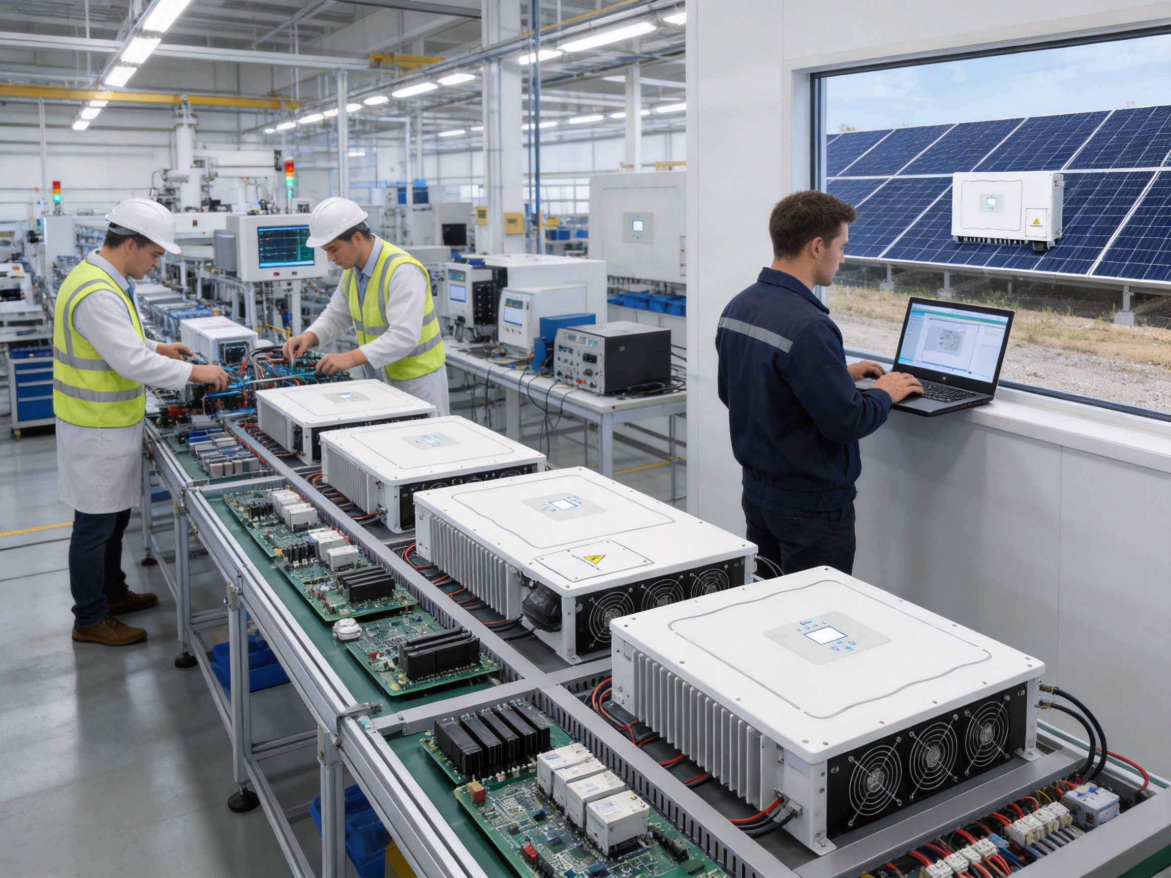
Commercial and industrial solar projects require inverters that can combine high power density, reliable grid interaction, flexible photovoltaic design, strong protection, and straightforward long-term maintenance. The SUN-70/75/80/90/100/110K-G03 series is designed for these requirements. It is a three-phase string inverter family covering rated power levels from 70 kW to 110 kW and offering up to six maximum power point trackers, wide operating voltage compatibility, intelligent monitoring options, and advanced protection functions.
For installers and system designers, the series provides a practical platform for rooftop, ground-mounted, agricultural, commercial, and industrial photovoltaic systems. Several power ratings are available within the same product family, allowing project developers to select an inverter according to array size, available roof area, grid capacity, and future expansion plans. This approach can simplify engineering, procurement, installation, commissioning, and service support across different project sizes.
The product is especially suited to demanding three-phase applications where high current capacity, multiple roof orientations, partial shading, grid support, and operational visibility are important. Its combination of up to 98.8% maximum efficiency, a 200–850 V MPPT voltage range, Type II surge protection on both the DC and AC sides, and a robust IP65 enclosure makes it a strong choice for challenging outdoor installations.
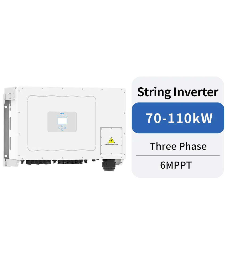
SUN-70/75/80/90/100/110K-G03(Bangladesh)
Product Overview and Application Positioning
The SUN-70/75/80/90/100/110K-G03 is a high-power three-phase string inverter intended for grid-connected photovoltaic systems. Its available models provide rated AC output powers of 70 kW, 75 kW, 80 kW, 90 kW, 100 kW, and 110 kW. This range allows a system designer to build a balanced inverter block without relying on a single oversized unit for every project.
Unlike a centralized inverter architecture, a string inverter system divides the photovoltaic array into multiple electrically independent input groups. Each string group can be connected to a dedicated MPPT channel, enabling the inverter to respond more effectively to differences in module orientation, tilt angle, temperature, soiling, and shading. This is particularly useful on commercial roofs that contain multiple roof sections or where nearby structures create uneven solar exposure.
The product supports four MPPT trackers in the 70 kW, 75 kW, and 80 kW configuration and six MPPT trackers in the 90 kW, 100 kW, and 110 kW configuration, according to the stated input arrangements. The six-MPPT version supports six string groups with four strings per tracker, while the four-MPPT configuration supports four strings per tracker. This architecture provides designers with meaningful flexibility when arranging high-power PV modules and selecting string lengths.
The inverter accepts a maximum PV input voltage of 1,000 V and has a rated PV input voltage of 600 V. Its start-up voltage is 250 V, while the MPPT operating range extends from 200 V to 850 V. This wide range helps the system maintain effective energy harvesting under changing weather conditions, including cool mornings, hot afternoons, and low-irradiance periods.
Applications include large commercial rooftops, factories, warehouses, logistics centers, shopping facilities, office complexes, schools, agricultural buildings, utility support installations, and distributed solar plants. The inverter can also be used in projects requiring zero-export control or virtual synchronous generator functionality, subject to the complete system design and applicable grid requirements.
Power Options for Scalable Project Design
One of the main advantages of this product family is its selection of six rated power levels. A 70 kW inverter may be appropriate for a smaller commercial roof or a site with limited grid capacity, while a 110 kW model can serve a larger PV array with fewer inverter units. Intermediate ratings allow system designers to optimize the relationship between PV capacity, AC interconnection limits, available installation space, and capital cost.
| Model | Rated AC Output Power | Maximum AC Apparent Power | Maximum PV Input Power |
| SUN-70K-G03 | 70 kW | 77 kVA | 91 kW |
| SUN-75K-G03 | 75 kW | 82.5 kVA | 97.5 kW |
| SUN-80K-G03 | 80 kW | 88 kVA | 104 kW |
| SUN-90K-G03 | 90 kW | 99 kVA | 135 kW |
| SUN-100K-G03 | 100 kW | 110 kVA | 150 kW |
| SUN-110K-G03 | 110 kW | 121 kVA | 150 kW |
The listed maximum PV input power values provide room for DC oversizing. Oversizing can improve annual energy yield by allowing the array to deliver more energy during low-light periods, when the inverter is not operating at its rated AC output. The appropriate DC-to-AC ratio depends on module technology, climate, roof orientation, clipping strategy, local regulations, and the project’s financial model. The inverter’s technical limits should always be checked before finalizing the array design.
Using one product family across different projects can also reduce operational complexity. Installers can develop standardized commissioning procedures, maintain a more consistent spare-parts inventory, and train service teams on a common platform. Owners operating several sites can benefit from similar monitoring, protection, and maintenance practices across the entire portfolio.
Multiple MPPT Trackers for Complex PV Arrays
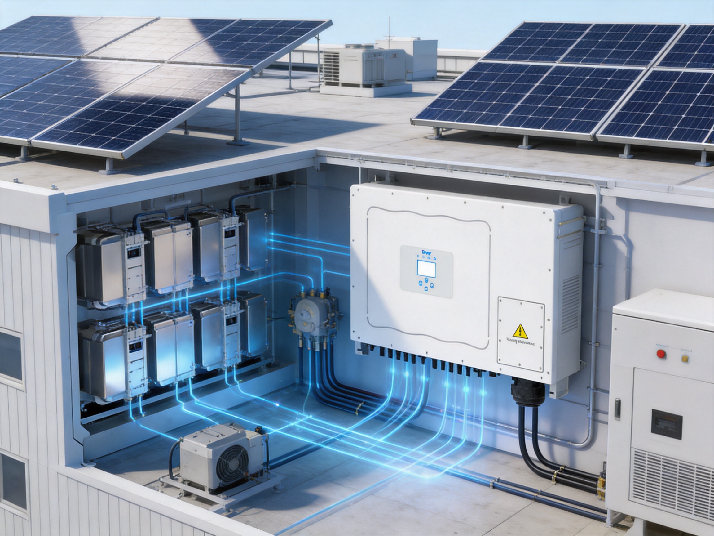
Multiple MPPT trackers are a central feature of the SUN-70/75/80/90/100/110K-G03 series. An MPPT tracker continuously adjusts the operating voltage and current of an assigned PV input group to identify the point at which the array produces its highest available power. When different portions of an array experience different conditions, separate trackers can reduce the energy losses that would occur if all strings were forced to operate at a common voltage.
Commercial and industrial buildings often have complicated roof geometries. A single site may include east-facing, south-facing, and west-facing sections, along with different roof pitches and areas affected by parapets, ventilation equipment, chimneys, water tanks, or neighboring buildings. The availability of four or six MPPT trackers allows the designer to assign electrically compatible strings to suitable trackers instead of combining all roof sections into one undifferentiated input group.
This flexibility can provide an advantage over products with fewer trackers, especially when the installation contains multiple orientations or partial shading. It also assists with string planning because the input channels can be distributed more logically across the available PV area. Better string organization can simplify fault diagnosis and improve the clarity of system documentation.
The inverter supports a maximum PV input voltage of 1,000 V, a 250 V start-up voltage, and an MPPT voltage range of 200–850 V. These parameters give designers substantial freedom when selecting the number of modules in each string. However, string design must account for the lowest expected temperature, because cold conditions increase module open-circuit voltage. It must also account for the highest expected operating temperature, module current, cable voltage drop, and the requirements of local electrical codes.
The stated maximum operating input current is arranged as 40 A per input group, while maximum short-circuit current capacity is listed as 60 A per input group. These values are useful when evaluating modern high-current PV modules. Compatibility should be verified against the module’s maximum power current, short-circuit current, bifacial gain, environmental correction factors, and parallel-string configuration.
High Conversion Efficiency and Energy Yield
Efficiency is one of the most important performance characteristics of a solar inverter because even a small percentage difference can affect the annual energy yield of a large commercial installation. The SUN-70/75/80/90/100/110K-G03 series reaches a maximum efficiency of up to 98.8%, with a Euro efficiency of up to 98.2% according to the available specification data. Its MPPT efficiency is greater than 99%.
Maximum efficiency describes the best conversion point under a particular operating condition, while weighted efficiency provides a broader indication of performance across a range of output levels. For a commercial PV system, the inverter may operate at full load around midday but at partial load during the morning, afternoon, cloudy periods, and winter months. High efficiency across a broad operating range can therefore have a more meaningful impact than peak efficiency alone.
The wide MPPT voltage range supports efficient operation as irradiance changes throughout the day. The inverter can continue tracking the array under conditions where the PV voltage varies significantly. This is valuable for systems with long strings, variable module temperatures, and seasonal differences in solar conditions.
Energy yield also depends on system design, module selection, cable sizing, ventilation, dust management, grid availability, and operational settings. The inverter contributes to yield through efficient DC-to-AC conversion, effective MPPT control, and the ability to divide complex arrays across multiple tracking channels. It does not eliminate losses caused by poor layout or shading, but it gives the designer more tools to minimize them.
Grid Compatibility and Advanced Grid Functions
The inverter is designed for three-phase grid connection using a 3L+N+PE configuration. It supports rated output voltages of 220/380 V and 230/400 V, with an output voltage range of 0.85 to 1.1 times the nominal voltage. The rated grid frequency can be 50 Hz or 60 Hz, with stated operating ranges of 45–55 Hz and 55–65 Hz respectively.
Its power factor adjustment range extends from 0.8 leading to 0.8 lagging. This capability can assist with reactive power management and grid support, depending on local utility requirements. Commercial sites with significant load variation may need an inverter that can respond to power factor requirements rather than simply delivering active power. The available range gives system engineers greater control over the AC-side operating profile.
The inverter also supports zero-export applications. In a zero-export system, control equipment measures the site’s import and export conditions and adjusts PV output so that energy is consumed locally rather than sent to the utility grid. This can be useful where export is restricted, compensation is unattractive, or the site owner wants to avoid reverse power flow.
Virtual synchronous generator functionality is another stated application. VSG operation is intended to provide grid-support behavior that resembles certain characteristics of conventional synchronous generation, such as controlled responses to grid conditions. The precise available functions depend on firmware, system configuration, grid rules, and external control equipment. Project engineers should confirm the required operating mode and certification before deployment.
The inverter supports a range of grid regulations, including IEC 61727, IEC 62116, CEI 0-21, CEI 0-16, EN 50549, NRS 097, RD 140, UNE 217002, OVE-Richtlinie R25, G99, VDE-AR-N 4105, and VDE-AR-N 4110. The applicable standard depends on the destination market and project interconnection category. Compliance documentation should be reviewed with the local utility, electrical consultant, or authority having jurisdiction.
Power Quality and Electrical Performance
Power quality is essential for commercial and industrial users because poor waveform quality can affect sensitive loads, transformers, protective devices, and other connected equipment. The inverter’s stated total current harmonic distortion is below 3%, and its DC injection current is below 0.5% of rated current. These specifications indicate attention to clean AC output and reduced risk of undesirable DC components entering the grid.
Low harmonic distortion can simplify the process of meeting interconnection requirements and help limit disturbances within the facility. Nevertheless, the final power quality of a complete PV installation depends on the inverter, transformer, cable system, grid impedance, adjacent loads, and other power electronics operating at the site.
The inverter can supply reactive power within its specified power factor range. This may support voltage regulation and help a project meet utility requirements. The operating settings should be established during commissioning, and any changes should be controlled by authorized technical personnel to prevent conflict with the grid operator’s requirements.
Because the product is a non-isolated inverter, system grounding, insulation monitoring, module technology, and local code requirements must be evaluated carefully. Non-isolated topology can support efficient and compact conversion, but it places greater importance on correct system protection, insulation quality, and compatible PV module design.
Protection and Safety Architecture
Safety is a critical selection factor for a high-power inverter. The SUN-70/75/80/90/100/110K-G03 series integrates multiple protection and monitoring functions intended to protect the inverter, the PV array, the AC network, and service personnel.
DC reverse polarity protection helps protect the inverter if PV conductors are connected incorrectly. AC output overcurrent protection, AC output overvoltage protection, and AC output short-circuit protection help manage abnormal electrical conditions on the grid side. Thermal protection monitors operating temperature and can respond when internal or external conditions exceed safe limits.
Insulation impedance detection checks the electrical isolation between the PV circuit and ground. This function is particularly important in non-isolated systems because insulation degradation can create safety risks, nuisance trips, or fault conditions. DC component monitoring helps identify unwanted direct-current content in the AC output.
Anti-islanding protection is included as standard. If the utility grid is disconnected, a grid-tied inverter must stop energizing the isolated network within the required time. Anti-islanding behavior helps protect utility personnel and equipment during maintenance or outage conditions.
Residual current detection adds another layer of monitoring for leakage-related conditions. The product also includes a DC switch, allowing the PV input circuit to be disconnected during service or emergency procedures when installed and operated according to the applicable safety instructions.
Type II surge protection is provided on both the DC and AC sides. Photovoltaic systems installed on large buildings are exposed to transient overvoltages caused by lightning activity, switching events, and disturbances on the electrical network. Surge protection does not replace a complete site lightning-protection system, but it can help limit transient energy reaching sensitive inverter components.
An arc fault circuit interrupter is available as an optional function. Arc faults can occur when damaged cables, loose connectors, or degraded contacts create localized electrical arcing. Where required by local codes or project specifications, the optional AFCI capability can provide an additional method of detecting and interrupting certain arc-related conditions.
An anti-PID function is also available as an option. Potential-induced degradation can reduce PV module performance under certain system voltage, humidity, and environmental conditions. The usefulness of anti-PID functionality depends on module construction, system grounding, climate, and the project’s long-term reliability objectives.
Outdoor Durability for Challenging Environments
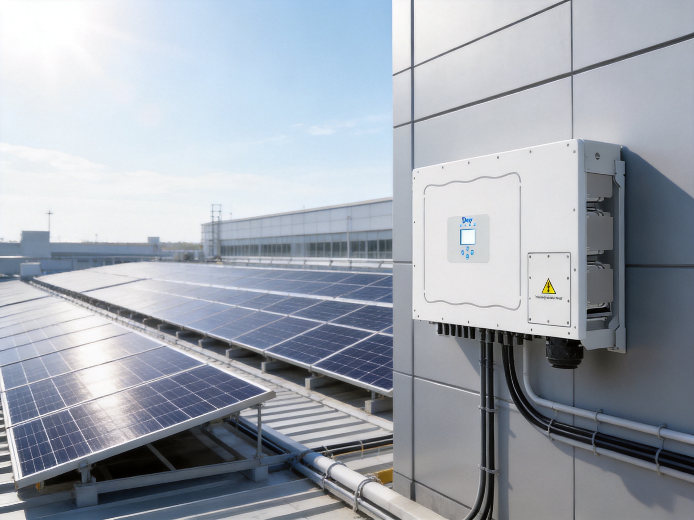
Commercial solar inverters are frequently installed outdoors or in semi-exposed plant rooms. The SUN-70/75/80/90/100/110K-G03 series has an IP65 ingress protection rating, indicating protection against dust ingress and water jets from specified directions. This rating supports outdoor installation when the inverter is mounted according to the manufacturer’s requirements and protected from conditions outside its stated operating limits.
The permitted operating temperature range is –25°C to +60°C. The inverter can therefore serve projects exposed to cold winter conditions as well as hot summer environments. At elevated temperatures, installers must follow the required clearances and ventilation provisions. Thermal derating may apply under particular combinations of ambient temperature, installation position, solar exposure, and output demand.
The permissible ambient humidity range is 0–100%, and the permitted altitude is up to 4,000 meters. These parameters broaden the potential application range, including humid coastal regions, tropical areas, elevated inland sites, and industrial environments. A project-specific assessment is still necessary where there is salt spray, corrosive gas, heavy dust, chemical contamination, or unusual weather exposure.
The listed noise level is no more than 55 dB. Intelligent air cooling helps manage internal temperature while maintaining a moderate acoustic profile for a high-power inverter. This can be important when equipment is installed near offices, schools, retail facilities, residential boundaries, or occupied industrial spaces.
The cabinet dimensions are approximately 824 mm wide, 516 mm high, and 312.7 mm deep, excluding connectors and brackets. The stated weight is 81 kg. These dimensions should be included in mechanical planning, access-route assessment, mounting design, lifting procedures, and service clearance calculations.
Monitoring and Communication Capabilities
Visibility into system performance is essential for commercial PV owners. The product provides RS485 and RS232 communication interfaces, along with Wi-Fi and LAN communication options. These interfaces allow the inverter to be incorporated into different monitoring architectures, including local commissioning tools, plant controllers, data loggers, and remote operation platforms.
String intelligent monitoring is available as an optional function. String-level visibility can help operators identify underperforming strings, open-circuit conditions, abnormal current, connector problems, localized shading, or module degradation. Without string monitoring, a fault may only become visible as a reduction in total inverter output. With more detailed information, maintenance teams can narrow the problem to a specific input group and reduce diagnostic time.
The inverter includes an LCD display with a resolution of 240 by 160 pixels. A local display can be useful during installation and commissioning, especially when communication networks are not yet configured. Technicians can review operating status, alarms, measurements, and basic settings directly at the equipment.
Remote monitoring is particularly valuable for distributed commercial portfolios. Operators can compare inverter performance across buildings, identify sites with unusual yield, review historical alarms, and schedule maintenance based on actual operating data. Communication security, data retention, user permissions, and network availability should be addressed during system design.
For large projects, monitoring data can be integrated with supervisory control and data acquisition systems or energy management platforms. The appropriate communication method depends on site topology, cable distance, electromagnetic conditions, network infrastructure, and the requirements of the operations team.
Installation and System Design Considerations
Correct installation is essential to achieving the inverter’s rated performance. The mounting surface must be structurally suitable for the equipment weight and environmental loads. Adequate clearances should be provided around the enclosure to support cooling, inspection, cable routing, and future maintenance.
The inverter should be installed in a location that is accessible to authorized personnel but protected from unnecessary mechanical impact. Direct exposure to intense reflected heat, corrosive emissions, standing water, or concentrated dust should be avoided. Although the enclosure is designed for outdoor use, appropriate site selection remains important for long-term reliability.
DC string design should be based on the module’s electrical characteristics at the lowest and highest expected operating temperatures. The maximum cold-weather open-circuit voltage must remain below the inverter’s 1,000 V maximum PV input voltage. The selected string arrangement must also remain within the relevant MPPT voltage range during normal operation.
Input current should be assessed under standard test conditions and under realistic conditions that may include bifacial gain, high irradiance, and parallel-string operation. Each MPPT tracker must remain within the stated current limits. Proper connector compatibility, polarity verification, cable sizing, and torque control are important during installation.
On the AC side, the rated and maximum output currents should be used to select conductors, circuit breakers, disconnect devices, busbars, and transformer capacity. The applicable current depends on voltage and operating conditions. For example, the listed rated output current values vary by nominal voltage, with the 110 kW model shown at 166.7 A or 159.4 A under the corresponding voltage conditions.
The grid connection uses three line conductors, neutral, and protective earth. Earthing and bonding must comply with local electrical codes. The AC and DC surge-protection arrangement should be coordinated with the broader site protection system, including external surge protective devices where required by the project design.
Commissioning should include polarity checks, insulation testing, protective-conductor verification, communication checks, grid-parameter confirmation, firmware review, alarm testing, and verification of the selected operating mode. Zero-export and reactive-power functions require special attention because incorrect meter orientation, communication failure, or unsuitable control settings can affect system operation.
Advantages Compared with Conventional Alternatives
The product’s competitive value comes from the combination of high output power and string-level flexibility. Traditional centralized inverter systems may place a large number of PV strings behind a common conversion stage. Such systems can be efficient and cost-effective in certain utility-scale applications, but they may provide less independent control when arrays have different orientations or shading conditions.
By providing four or six MPPT trackers, the SUN-70/75/80/90/100/110K-G03 series can accommodate more varied array layouts than many high-power products with fewer trackers. This can reduce mismatch losses and improve design flexibility on complex commercial roofs.
Another advantage is the broad model range. A supplier offering only one large rating may force designers to use more units than necessary or accept an oversized AC system. The six available ratings make it easier to match inverter capacity to the PV array and facility load. Standardizing on one family also reduces training and maintenance complexity.
The product offers a high maximum efficiency of up to 98.8% and an MPPT efficiency above 99%. These figures support strong energy conversion performance. The wide MPPT voltage range and high maximum PV input voltage further support flexible string configuration and DC oversizing strategies.
The inclusion of Type II DC and AC surge protection, anti-islanding protection, residual current detection, thermal protection, and insulation monitoring creates a comprehensive integrated safety package. Optional AFCI and anti-PID functions give project developers the ability to adapt the protection configuration to local requirements and technical priorities.
Zero-export capability and VSG application support expand the inverter’s usefulness beyond basic energy conversion. These functions can help address grid constraints, commercial self-consumption objectives, and more advanced distributed-energy applications.
Some competing products may offer similar individual specifications, but project performance depends on the total combination of electrical flexibility, environmental durability, protection, monitoring, compliance, and serviceability. The value of this series lies in providing these features within one high-power platform.
Manufacturing Strengths and Engineering Capability
The manufacturer is described as a comprehensive technology enterprise integrating research and development, design, production, sales, and service. This vertically coordinated structure can provide important advantages in product development and lifecycle support. When engineering, manufacturing, testing, and service teams operate within one organization, design feedback can move more efficiently from field experience into future product improvements.
The company was founded in 2000 and entered a new phase of growth after being listed on the Shanghai Stock Exchange in 2021. Its business covers photovoltaic inverters, energy storage systems, microinverters, environmental appliances, and related energy technologies. This broad technical portfolio gives the organization experience across power conversion, thermal management, digital control, communication, and energy management.
The stated product range includes string inverters from 1 kW to 136 kW, energy storage inverters from 3 kW to 80 kW, and microinverters from 300 W to 2.2 kW. Such a range suggests the ability to develop products for residential, commercial, industrial, and utility-related applications rather than focusing on only one market segment.
Advanced manufacturing for high-power inverters requires disciplined control of electronic assembly, mechanical integration, thermal design, firmware deployment, electrical testing, and final inspection. A modern production process typically begins with controlled incoming-material inspection. Power semiconductors, capacitors, magnetic components, circuit boards, connectors, cooling components, enclosures, and protection devices must meet defined specifications before entering assembly.
Electronic assemblies require accurate placement and soldering of components. Automated surface-mount technology can improve repeatability, while optical inspection and electrical testing help identify assembly defects. High-power boards also require attention to creepage distance, clearance, conductor geometry, heat dissipation, insulation systems, and mechanical reinforcement.
Power-stage assembly is particularly important because the inverter must process substantial DC and AC current over many years. Production controls should verify busbar connections, terminal torque, insulation barriers, thermal interfaces, and the correct installation of switching devices and passive components. These details directly affect efficiency, reliability, and long-term thermal behavior.
Thermal management is another area where manufacturing quality matters. Intelligent air cooling depends not only on fans but also on heat-sink design, airflow paths, sensor placement, filter strategy, enclosure geometry, and control software. Consistent assembly is necessary to ensure that air can move through the intended channels and that heat-generating components remain within safe operating conditions.
Final testing for a high-power string inverter can include insulation resistance checks, dielectric withstand tests, protective-function verification, communication tests, simulated fault responses, MPPT operation checks, AC waveform analysis, efficiency verification, and temperature-related validation. Production traceability can help connect the finished unit to key materials, software versions, test records, and quality inspections.
Research and development capability also contributes to manufacturing strength. Power electronics products require coordination among electrical engineers, mechanical engineers, embedded-software developers, grid-compliance specialists, reliability engineers, and manufacturing teams. The ability to manage these disciplines together can accelerate product updates and improve compatibility with changing grid standards.
The company’s international presence, with products sold in more than 140 countries and regions, also provides exposure to diverse climates, grid codes, installation practices, and customer expectations. This global operating experience can support the development of products that are adaptable to different voltage systems, frequencies, protection requirements, and environmental conditions.
Reliability, Serviceability, and Lifecycle Value
Commercial PV owners evaluate more than the initial purchase price. They also consider energy yield, downtime risk, maintenance labor, spare-parts logistics, monitoring quality, and warranty support. The inverter includes a standard five-year warranty, with extended warranty options available. Project owners can therefore select additional coverage according to financing terms, asset-holding period, insurance requirements, and service strategy.
String architecture can improve serviceability because a fault in one input group does not necessarily stop the entire photovoltaic plant. Other input groups may continue operating, depending on the nature of the fault and the inverter’s protective response. This partial-operation characteristic can reduce the impact of localized issues compared with architectures where a broader section of the array is dependent on one conversion unit.
Remote monitoring and optional string intelligent monitoring can further reduce the time between fault occurrence and corrective action. Service teams can use operating data to distinguish between inverter faults, grid events, string problems, communication failures, and environmental conditions. This helps avoid unnecessary site visits and allows technicians to arrive with more suitable tools and replacement parts.
Long-term reliability also depends on preventive maintenance. Installers and operators should periodically inspect cable connections, ventilation paths, cooling components, surge protection indicators, enclosure seals, mounting points, and communication equipment. Maintenance intervals should be adapted to the site environment, especially where dust, salt, humidity, or industrial contamination is present.
Firmware and configuration management should be handled under controlled procedures. Updates may improve performance, address compliance changes, or add monitoring functions, but they should be tested and documented before deployment across a large project portfolio.
Suitability for Bangladesh and Similar Markets
The Bangladesh-specific product designation indicates a configuration intended for the requirements of that market. Bangladesh includes hot and humid conditions, seasonal rainfall, dense urban development, industrial facilities, agricultural operations, and a growing interest in distributed solar generation. These conditions make environmental protection, thermal management, reliable grid interaction, and flexible rooftop design especially relevant.
The product’s operating temperature range, high humidity tolerance, IP65 enclosure, and intelligent cooling support deployment in demanding climates. However, the installation location should still be selected carefully. Equipment should not be placed where floodwater can reach the enclosure, where ventilation is blocked, or where corrosive contaminants accumulate.
Many commercial and industrial buildings in Bangladesh may have roofs with multiple orientations, equipment obstructions, and limited space for electrical infrastructure. Four or six MPPT trackers can help designers manage these conditions more effectively. The available 70–110 kW range also allows the system to be scaled according to the facility’s load profile and grid connection capacity.
Zero-export functionality may be valuable for facilities that primarily want to offset on-site electricity consumption. Before implementation, the project team should verify local utility rules, metering arrangements, export limitations, protection requirements, and the availability of appropriate control meters and communication links.
Because environmental and grid conditions vary from site to site, a complete feasibility assessment remains essential. The inverter should be matched with suitable PV modules, mounting structures, AC equipment, transformers, protection devices, monitoring systems, and maintenance procedures.
Recommended Project Selection Process
The first step in selecting a model is to determine the desired AC capacity and the facility’s available grid connection. The 70 kW, 75 kW, and 80 kW models may suit smaller commercial applications, while the 90 kW, 100 kW, and 110 kW models can reduce the number of inverter units required for larger arrays.
The second step is to evaluate the PV array. Designers should calculate the expected DC capacity, module voltage range, short-circuit current, operating current, string length, parallel-string count, and environmental correction factors. Roof orientation and shading conditions should be mapped before assigning strings to MPPT trackers.
The third step is to review the AC infrastructure. This includes transformer rating, main distribution-board capacity, cable length, voltage drop, circuit-breaker selection, fault current, neutral arrangement, protective earth, and the requirements of the utility interconnection agreement.
The fourth step is to determine the required operating functions. Some projects need simple grid-connected operation, while others require zero-export control, reactive-power management, VSG functionality, string monitoring, AFCI, or anti-PID support. Optional functions should be identified early so that procurement and commissioning plans remain consistent.
The fifth step is to define environmental and service conditions. Temperature, humidity, altitude, dust, salt exposure, accessibility, noise sensitivity, and maintenance capability should all be considered. These factors can influence enclosure location, cooling requirements, cleaning schedules, warranty planning, and the selection of extended service coverage.
Finally, the project team should confirm applicable certifications and grid regulations. A product may support multiple international standards, but the exact documentation required for a particular project depends on the country, utility, voltage level, and installation category.
Technical Specification Summary
| Specification | Value |
| Product type | Three-phase string inverter |
| Rated power range | 70–110 kW |
| Maximum PV input voltage | 1,000 V |
| Start-up voltage | 250 V |
| MPPT voltage range | 200–850 V |
| Rated PV input voltage | 600 V |
| Number of MPPT trackers | Four or six, depending on model configuration |
| Maximum efficiency | Up to 98.8% |
| Euro efficiency | Up to 98.2% |
| MPPT efficiency | Greater than 99% |
| AC grid connection | 3L+N+PE |
| Output voltage | 220/380 V or 230/400 V |
| Grid frequency | 50 Hz or 60 Hz |
| Power factor range | 0.8 leading to 0.8 lagging |
| Total current harmonic distortion | Less than 3% |
| Surge protection | Type II DC and Type II AC |
| Communication | RS485, RS232, Wi-Fi, and LAN |
| Operating temperature | –25°C to +60°C |
| Maximum permissible altitude | 4,000 m |
| Ingress protection | IP65 |
| Cooling method | Intelligent air cooling |
| Display | 240 × 160 LCD |
| Warranty | Standard five years, with extended warranty available |
Frequently Asked Questions
What type of solar system is this inverter designed for?
It is designed for high-power, three-phase, grid-connected photovoltaic systems. Typical applications include commercial rooftops, industrial facilities, warehouses, agricultural buildings, and distributed solar plants.
What power ratings are available?
The series includes 70 kW, 75 kW, 80 kW, 90 kW, 100 kW, and 110 kW models. This selection allows the inverter capacity to be matched more closely with the PV array and facility grid connection.
How many MPPT trackers are provided?
The product family provides four or six MPPT trackers depending on the model configuration. The higher-capacity configuration supports six trackers, which can be useful for arrays with multiple orientations or shading conditions.
Can the inverter be used with high-power PV modules?
The inverter provides high current input capability, with the stated maximum operating current arranged at 40 A per input group and maximum short-circuit current at 60 A per input group. Module current, parallel-string design, bifacial gain, and temperature factors must be checked before final selection.
What is the maximum PV input voltage?
The maximum PV input voltage is 1,000 V. The start-up voltage is 250 V, and the MPPT voltage range is 200–850 V. String voltage must remain within the permitted limits under the full expected temperature range.
Does the inverter support zero-export operation?
Yes. Zero-export application is listed as one of the product’s supported functions. The complete system normally requires suitable metering and control equipment, and the configuration must comply with local utility requirements.
Does it support reactive power control?
Yes. The stated power factor adjustment range is 0.8 leading to 0.8 lagging. The final reactive-power settings should be established according to the grid connection agreement and local regulations.
What protection functions are included?
Protection functions include DC reverse polarity protection, AC overcurrent protection, AC overvoltage protection, AC short-circuit protection, thermal protection, insulation impedance detection, DC component monitoring, anti-islanding protection, residual current detection, a DC switch, and Type II surge protection on both the DC and AC sides.
Are AFCI and anti-PID functions standard?
AFCI and anti-PID functions are listed as optional. Their inclusion should be specified during project planning according to local codes, module requirements, climate, and the owner’s reliability objectives.
Can the inverter be installed outdoors?
Yes. The IP65 enclosure and operating temperature range of –25°C to +60°C support outdoor installation when the inverter is mounted correctly and protected from unsuitable site conditions. Proper clearance, ventilation, drainage, and service access are still required.
What communication interfaces are available?
The inverter provides RS485, RS232, Wi-Fi, and LAN interfaces. An LCD display with 240 by 160 resolution is also included for local status and commissioning information.
What is string intelligent monitoring?
String intelligent monitoring is an optional function that can provide more detailed information about the performance of individual input groups. It can help identify abnormal current, string faults, shading, connector problems, or underperforming sections of the PV array.
What is the warranty period?
The standard warranty is five years, with extended warranty options available. Project owners should select coverage according to the planned operating period, financing requirements, service model, and risk-management strategy.
What should be checked before installation?
Before installation, the project team should verify PV string voltage and current, AC current, grid voltage and frequency, grounding, protection coordination, cable sizes, mounting strength, environmental conditions, communication requirements, and the applicable grid standards.
Conclusion
The SUN-70/75/80/90/100/110K-G03 series provides a comprehensive platform for high-power commercial and industrial solar generation. Its six available power ratings support scalable project development, while four or six MPPT trackers provide flexibility for complex PV layouts. A maximum efficiency of up to 98.8%, MPPT efficiency above 99%, and a wide 200–850 V tracking range support effective energy conversion across changing operating conditions.
The inverter is also designed for demanding grid-connected applications. Its three-phase output, adjustable power factor, low stated harmonic distortion, zero-export capability, and VSG application support make it suitable for projects with more advanced energy-management requirements.
Protection and durability are equally important strengths. Type II DC and AC surge protection, anti-islanding protection, insulation monitoring, residual current detection, thermal protection, and optional AFCI and anti-PID functions provide a strong foundation for safe operation. The IP65 enclosure, wide temperature range, high-altitude capability, and intelligent air cooling support reliable deployment across varied environments.
Behind the product is a manufacturer with experience across research and development, design, production, sales, and service, as well as a broad portfolio covering photovoltaic inverters, energy storage, microinverters, and energy-management technologies. This integrated capability can support product innovation, manufacturing consistency, international compliance, and long-term customer service.
For developers seeking a flexible and scalable inverter platform, the series offers a balanced combination of electrical performance, system protection, monitoring, environmental resilience, and manufacturing support. Final product selection should always be based on a complete engineering review of the PV array, site conditions, grid requirements, protection design, and applicable regulations.
References
1. Product datasheet for the SUN-70/75/80/90/100/110K-G03 three-phase string inverter series.
2. Product installation and operation manual for the SUN-70/75/80/90/100/110K-G03 series.
3. IEC 61727, Photovoltaic Systems: Utility Interface Characteristics.
4. IEC 62116, Utility-Interconnected Photovoltaic Inverters: Test Procedure of Islanding Prevention Measures.
5. IEC 62109-1 and IEC 62109-2, Safety of Power Converters for Use in Photovoltaic Power Systems.
6. IEC 61000 series, Electromagnetic Compatibility Requirements for Power Conversion Equipment.
7. EN 50549, Requirements for Generators to Be Connected in Parallel with Distribution Networks.
8. VDE-AR-N 4105 and VDE-AR-N 4110, Technical Requirements for the Connection of Power Generating Plants to Electrical Networks.
9. General engineering practices for commercial and industrial photovoltaic system design, commissioning, operation, and maintenance.
Product: SUN-70/75/80/90/100/110K-G03(Bangladesh)
PREV:Wireless Energy Management Systems for Smarter Solar Power Utilization
NEXT:Scalable 100kW–2.5MW Commercial and Industrial Energy Storage Solution
Share
Product recommendations
news recommendations
-
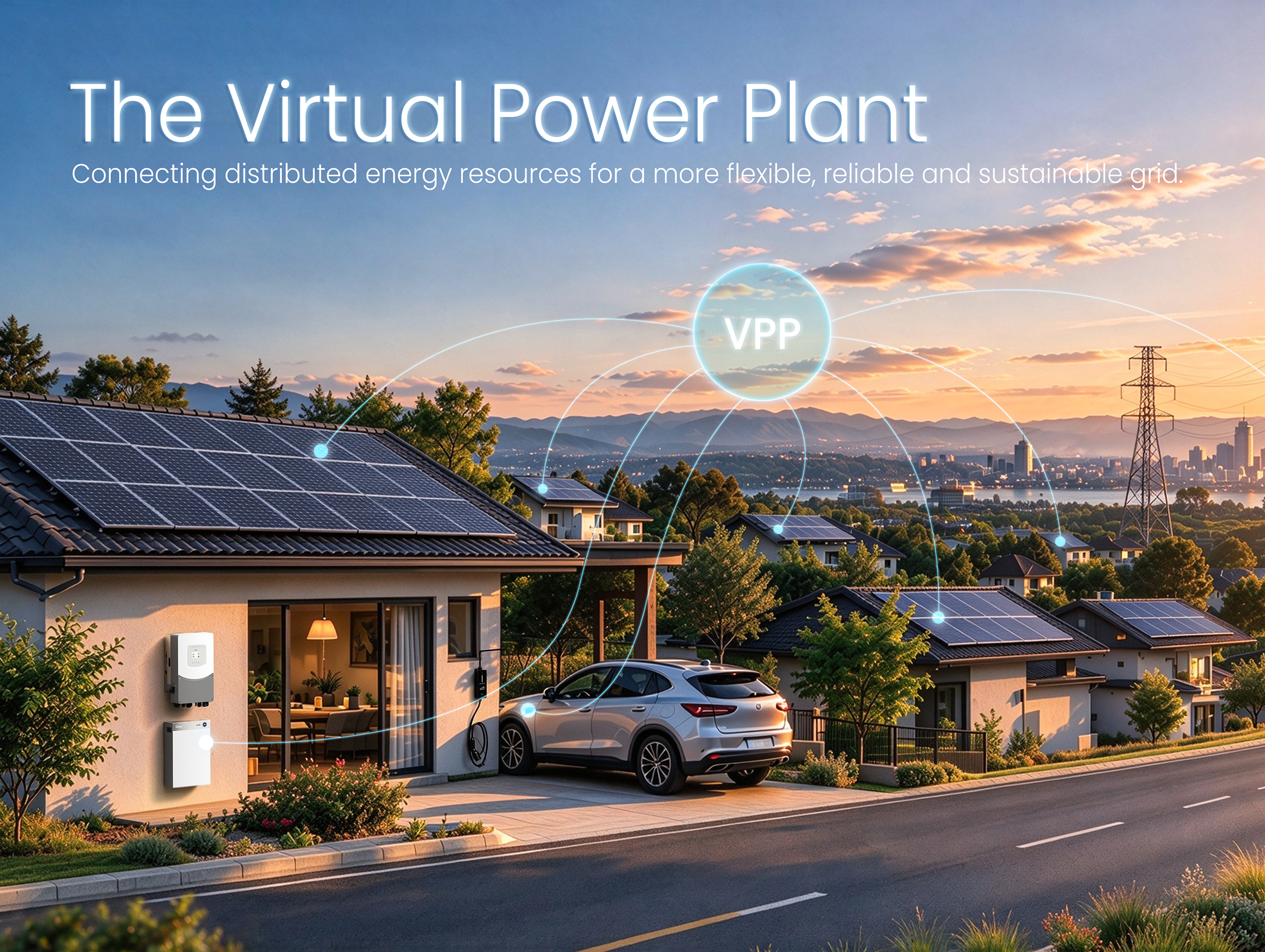 From Centralized Grids to Virtual Power Plants: The Next Evolution of the Power System
For more than a century, power systems around the world have relied on a centralized model. Large p...
-
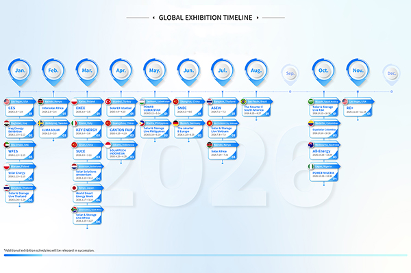 GLOBAL EXHIBITION TIMELINE
*Click to view larger image
-
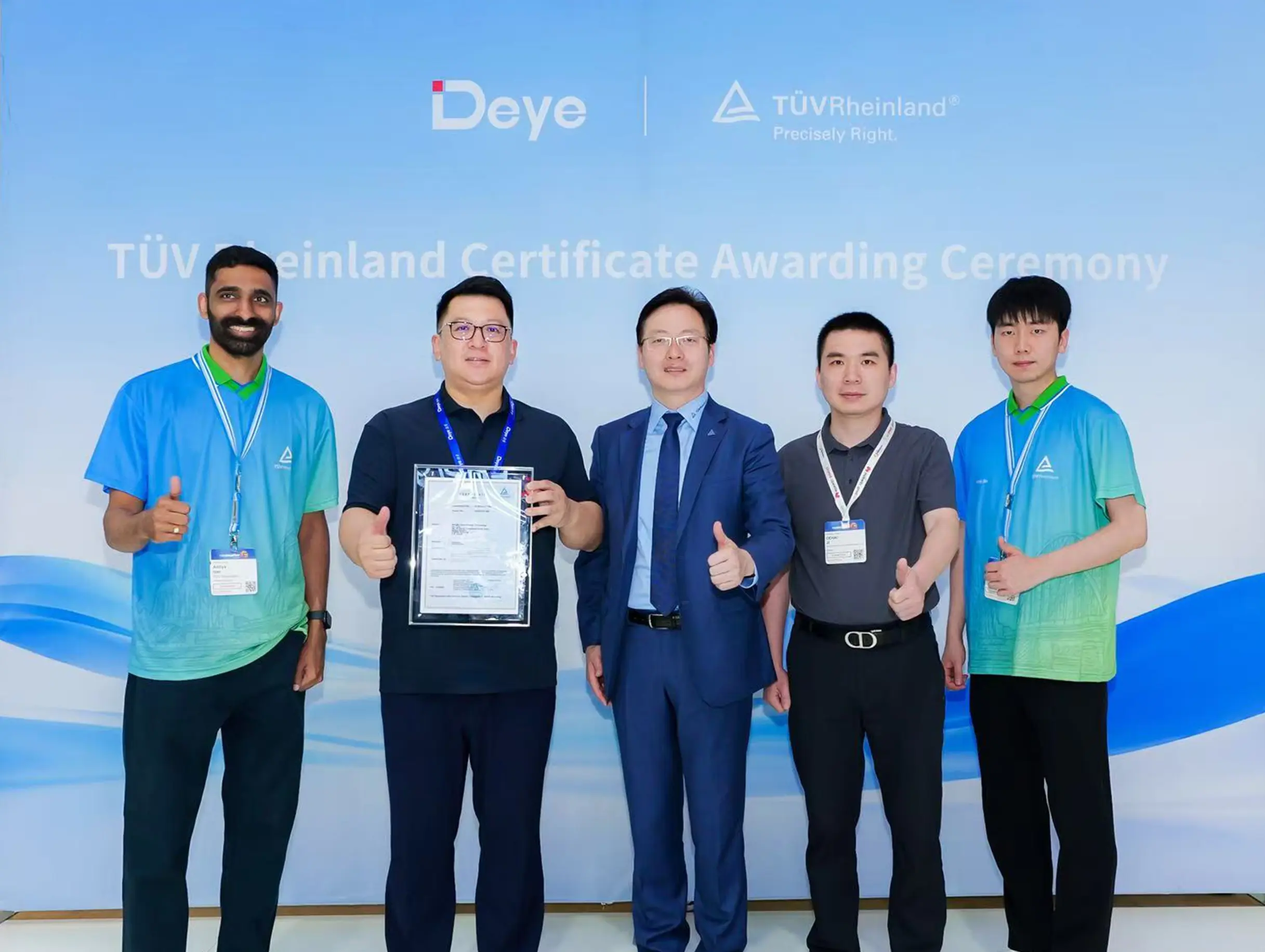 Deye Secures Multiple TÜV Rheinland Certifications at The smarter E Europe
On June 23, the opening day of The smarter E Europe 2026, Deye was officially awarded several presti...

Copyright@ 2024.Ningbo Deye Inverter Technology Co.,Ltd. All rights reserved. Solar Inverter Manufacturer
