
 Online Shop
 English
 China - 简体中文
 Global - English
 Brazil - Português
 Netherlands - Dutch
 Italy - Italiano
 Germany - Deutsch
 Spain - Español
 France - Français
 Vietnam - Tiếng Việt
 Poland - Polski
 Australia - English
 Japan - 日本語
Zhuo Yiran — Senior After-Sales Service Engineer, Energy Storage Systems

Wireless Energy Management Systems for Smarter Solar Power Utilization
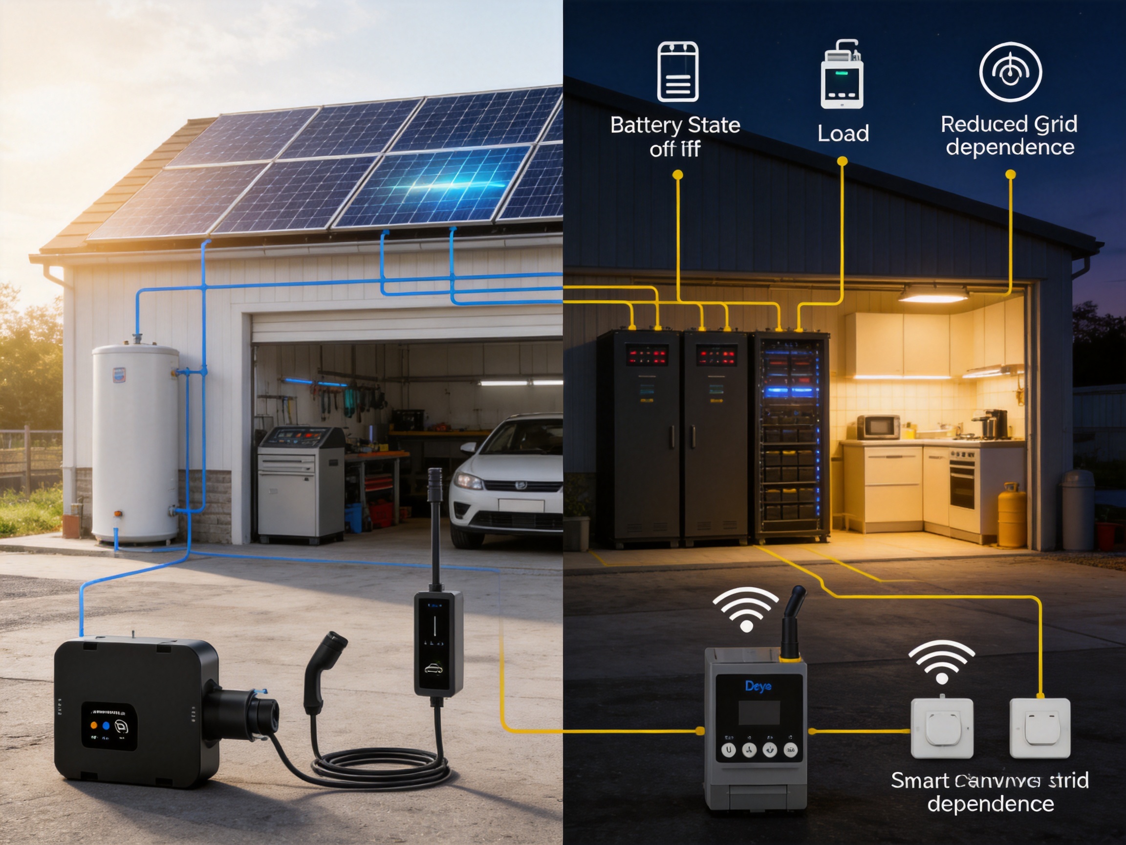
The rapid growth of residential and small commercial solar power has changed the way electricity is generated, stored, and consumed. Solar panels and hybrid inverters can produce and manage substantial amounts of energy, but the value of a solar installation depends on more than generation capacity alone. Homeowners and businesses also need to coordinate batteries, electric vehicle charging, water heating, appliances, and other loads so that available solar power is used as efficiently as possible.
A wireless energy management system provides the control layer required to achieve this objective. By combining accurate energy measurement, low-latency LoRa communication, smart switching, load prioritization, and time- and state-of-charge-based charging strategies, the system helps users increase self-consumption and reduce dependence on grid electricity. It is designed to work with hybrid inverter installations and can coordinate a range of smart devices through a flexible wireless architecture.
The system discussed in this article is built around several coordinated devices: the SUN-SMART-CT01 energy measurement and control unit, the SUN-SMART-TX01 wireless transmitter, the SUN-SMART-SWITCH01P3 smart switch, the SUN-SMART-PLUG01-F smart plug, and compatible electric vehicle charging equipment. Together, these components create an energy management ecosystem rather than a standalone meter or remote switch.
Its key advantages include offline operation, support for hybrid inverter systems, long-range LoRa communication, accurate electrical measurement, intelligent load classification, and multiple methods for controlling flexible loads. The system also benefits from the manufacturer’s broad experience in photovoltaic inverters, energy storage systems, electrical control products, and large-scale production management.
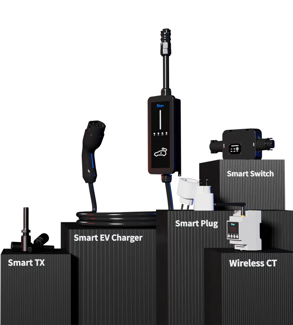
Wireless energy management system
What Is a Wireless Energy Management System?
A wireless energy management system is a coordinated hardware and software solution that monitors energy flows and automatically controls selected electrical loads. It connects the solar inverter, battery system, household or commercial loads, and selected smart devices so that electricity can be used according to defined priorities.
In a conventional solar installation, the inverter may convert and manage energy, but the system may not know whether a particular appliance is essential, whether an electric vehicle should be charged immediately, or whether a flexible load should wait until battery state of charge reaches a preferred level. Without intelligent coordination, excess solar energy may be exported to the grid while the property later purchases electricity to operate the same equipment.
The wireless energy management system addresses this issue by enabling users or installers to define operating rules. Essential loads can be kept active, while non-essential or flexible loads can be switched on when sufficient solar power is available. Battery charging and electric vehicle charging can also be scheduled according to time periods, energy prices, solar availability, or battery state of charge.
The system is especially useful for properties equipped with hybrid inverters. A hybrid inverter can manage solar generation, battery storage, and grid interaction, while the energy management system adds more detailed control over the loads connected to the installation. This division of functions allows each part of the system to perform its role efficiently.
From Energy Monitoring to Energy Control
Basic energy monitoring systems display voltage, current, power, and energy consumption. This information is useful, but monitoring alone does not automatically improve energy performance. A more advanced system must be able to interpret operating conditions and initiate appropriate actions.
The wireless energy management system combines measurement with control. The SUN-SMART-CT01 measures electrical parameters and communicates with associated devices. The transmitter and wireless switching products then extend control to selected appliances, circuits, and charging equipment. This creates a feedback loop in which the system can measure energy conditions, apply user-defined priorities, and adjust connected loads.
Such a design is valuable in installations where loads change throughout the day. For example, an electric vehicle may be connected during the afternoon, a heat pump may operate in the evening, and household appliances may create short periods of high demand. Smart coordination allows the system to respond to these changing conditions without requiring users to manage every device manually.
Core Product Architecture
The product family is made up of complementary components that can be deployed together as a complete solution or selected according to the requirements of an individual installation.
SUN-SMART-CT01 Energy Measurement and Management Unit
The SUN-SMART-CT01 is the central measurement device in the system. It supports single-phase and three-phase electrical connections. The specified connection configurations are L1/N for single-phase installations and L1/L2/L3/N for three-phase installations.
The device uses current transformers with a secondary current of 50 mA and operates over an AC voltage range of 85 to 300 V line-to-neutral. It supports both 50 Hz and 60 Hz electrical systems within the stated frequency ranges. Its self-consumption is no more than 2 W, helping maintain low operating overhead.
Measurement accuracy is a significant advantage for an energy management device. The stated accuracy values are ±0.1 V for voltage, ±0.01 A for current, ±0.01 Hz for frequency, and ±1 W for power. Accurate measurement enables more reliable decisions when the system is determining whether surplus solar energy is available or whether a load should be delayed.
The CT01 includes LoRa and RS485 communication interfaces and provides an LCD display. Displayed information includes voltage, current, active power, reactive power, frequency, power factor, and energy. This combination of local visibility and network communication is practical for commissioning, maintenance, and day-to-day verification.
The device is designed for DIN-rail mounting, making it suitable for electrical distribution cabinets and control panels. Its dimensions are 53 by 96 by 64 millimeters, and its weight is approximately 0.15 kilograms. It operates from -40°C to +60°C, supports installation at altitudes up to 4,000 meters, and carries an IP20 rating. The stated warranty period is five years.
SUN-SMART-TX01 Wireless Transmitter
The SUN-SMART-TX01 extends communication between the energy management system and compatible field devices. It uses a 5 V DC input and communicates through LoRa. Its stated communication distance is approximately 200 meters in barrier-free conditions, allowing the system to serve installations where the inverter, electrical cabinet, and controlled loads are not located in the same room.
The transmitter has a built-in antenna with a gain of 0.56 dBi and operates in the 863 to 870 MHz frequency range. It is designed for an operating temperature range of -40°C to +60°C and a permissible ambient humidity range of 0 to 100 percent, subject to the specified installation conditions.
The transmitter measures 137.8 by 31.3 by 31.3 millimeters and weighs approximately 45.8 grams. Its compact form simplifies installation near suitable control equipment. It has an IP20 rating before installation and an IP65 rating after installation when correctly protected by the applicable installation arrangement. The stated warranty is two years, and the product is specified to IEC/EN 62368-1.
SUN-SMART-SWITCH01P3 Smart Switch
The SUN-SMART-SWITCH01P3 is intended for switching larger electrical loads than a typical plug-in accessory. It supports single-phase and three-phase connection configurations and operates within a phase-voltage range of 94 to 238 V AC. Its maximum phase current is 25 A AC.
The unit uses a connector plug-in connection and communicates via LoRa. With a stated barrier-free range of approximately 200 meters, it can be placed close to the load while receiving energy management commands wirelessly. This is useful when a controlled appliance or circuit is located away from the main inverter cabinet.
The switch is rated for an operating temperature range of -40°C to +45°C and a humidity range of 0 to 100 percent relative humidity. Its IP65 protection rating supports use in appropriate indoor or sheltered environments where protection from dust and water ingress is required. It is classified as Class I equipment and is designed for altitudes up to 4,000 meters.
The device measures 96.7 by 204.7 by 37.7 millimeters and weighs approximately 0.4 kilograms. Its specified warranty is five years, and its standard is IEC/EN 61010-1. The combination of a 25 A switching capacity, three-phase compatibility, wireless communication, and outdoor-capable enclosure makes it suitable for a broad range of managed loads.
SUN-SMART-PLUG01-F Smart Plug
The SUN-SMART-PLUG01-F offers a simpler plug-type option for compatible appliances. It is rated for 220 to 250 V AC and a maximum current of 16 A AC. The product is suitable for loads that can be connected through a standard plug arrangement and do not require the higher current capacity or fixed wiring associated with the smart switch.
The smart plug communicates through LoRa and provides an approximate barrier-free communication distance of 200 meters. It has an internal antenna and operates in the 863 to 870 MHz frequency range. Its stated antenna gain is approximately 3.23 dBi at 868 MHz.
The plug operates from -40°C to +60°C and has an IP20 rating. It is Class I equipment, supports installation at altitudes up to 3,000 meters, and measures 51.2 by 51.2 by 64 millimeters. Its weight is approximately 0.08 kilograms. The stated warranty is five years, and its referenced standards include VDE 0620-2-1 and EN 61058.
Compatible Electric Vehicle Charging Equipment
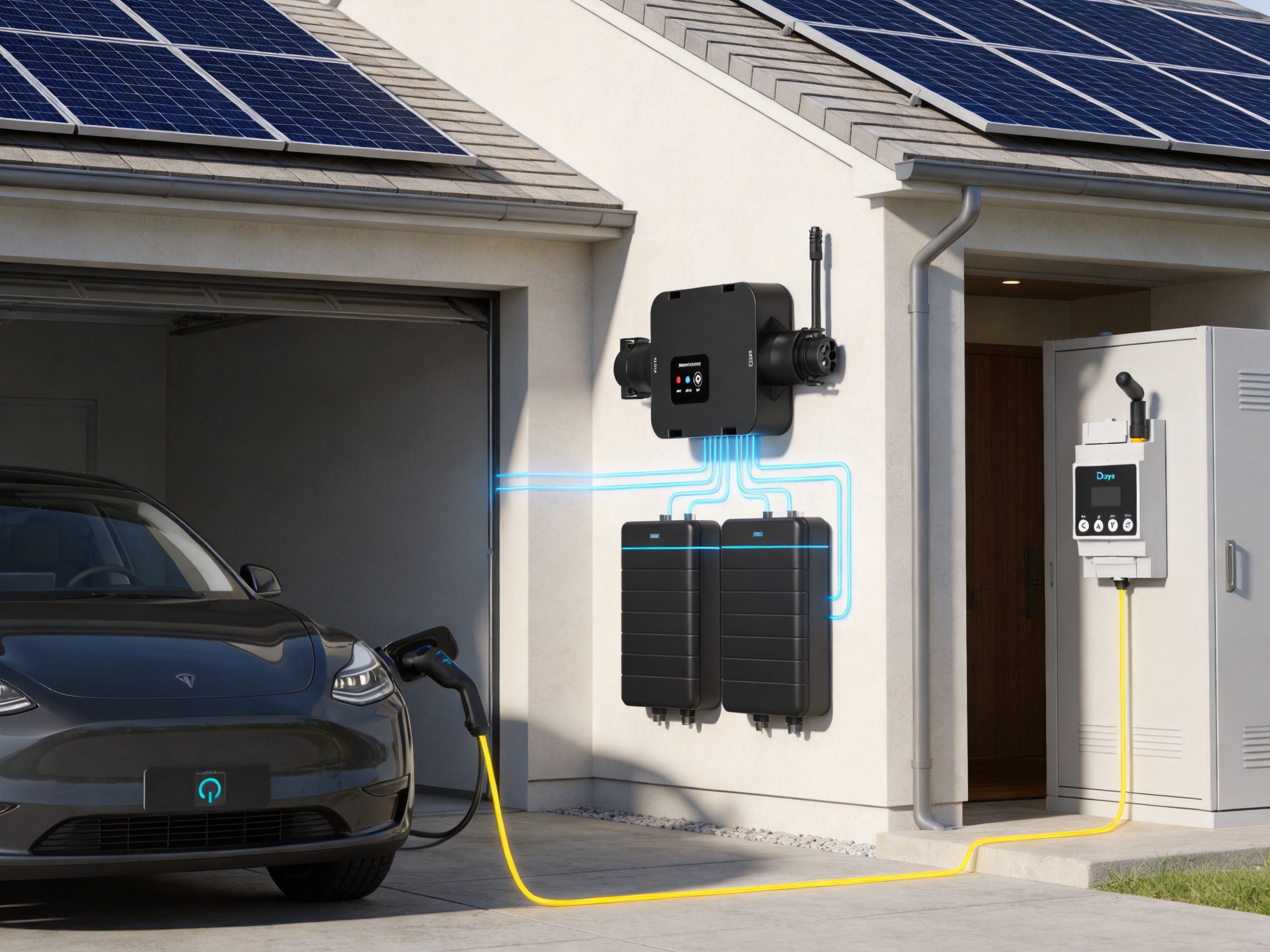
Electric vehicle charging is one of the most important flexible loads in a modern solar energy system. The compatible AC charging products include 11 kW and 22 kW models for European applications. Depending on the model and electrical configuration, the charging equipment can support 7 kW single-phase charging, 11 kW three-phase charging, or 22 kW three-phase charging.
The charging equipment supports plug-and-charge operation, charging after scanning, and scheduled charging. It includes over-temperature, low-temperature, over-voltage, under-voltage, short-circuit, overload, earth-fault, and leakage-current protection. A DC 6 mA leakage-current protection function and Type II surge protection are also specified.
The charging unit operates from -40°C to +55°C, supports 5 to 95 percent non-condensing humidity, and is designed for altitudes below 3,000 meters. Its IP66 rating provides a high level of enclosure protection. The unit has a noise level of no more than 25 dB, a cabinet size of 104 by 264 by 57.5 millimeters, and a cable length of approximately 4.2 meters.
Communication options include LoRa, Wi-Fi, and Bluetooth Low Energy. These interfaces allow the charging equipment to participate in a larger energy management strategy while retaining convenient local or wireless access.
Major Benefits Compared with Conventional Solutions
Low-Latency Load Response
Energy management decisions are most effective when devices respond promptly. A long delay between a change in solar production and a load-control action can cause unnecessary grid import or missed opportunities to use surplus energy.
The system’s LoRa-based communication architecture is designed for responsive wireless coordination. This helps the system react to changes in consumption, battery state of charge, or available photovoltaic power without relying solely on cloud-based commands. Low-latency communication is particularly useful for loads that need to be switched according to current energy conditions.
Compared with solutions that depend entirely on internet connectivity, a local wireless arrangement can reduce communication delays and simplify operation in locations with inconsistent broadband service. The system can continue to perform defined control tasks within the local installation.
Offline Operation
Offline operation is an important distinction in energy control. Internet access may be interrupted by router failure, service outages, poor signal coverage, or maintenance. If a system depends exclusively on a remote server, its automation functions may be limited during such interruptions.
The wireless energy management system is designed to support operation without continuous cloud dependence. Local communication between the energy measurement unit, transmitter, smart switch, smart plug, and compatible charging equipment allows configured control strategies to continue operating within the installation.
This does not eliminate the value of remote monitoring or application-based management where available. Instead, it provides an additional layer of resilience. Users can benefit from connected features during normal operation while retaining important local control functions when internet access is unavailable.
Long-Range LoRa Communication
LoRa communication is well suited to distributed energy devices because it can provide long communication distances with relatively low power requirements. The stated range of approximately 200 meters without barriers is sufficient for many homes, workshops, farm buildings, and small commercial properties.
Wireless communication reduces the need to install dedicated communication cabling between every controlled load and the inverter or distribution cabinet. This can simplify retrofit projects and lower installation disruption. It is also useful when the electrical equipment is spread across different rooms, floors, garages, or outbuildings.
Actual communication performance depends on building materials, walls, metal structures, interference, antenna placement, and local regulations. Nevertheless, the use of LoRa provides a practical alternative to short-range wireless protocols that may have difficulty passing through multiple structural barriers.
Compatibility with Hybrid Inverters
Compatibility with hybrid inverters is central to the system’s value. Hybrid inverters combine solar generation, battery storage, and grid management, but effective energy utilization requires information about the loads connected to the property.
The system is specified to support all compatible hybrid inverters in the manufacturer’s range. This broad compatibility simplifies product selection for installers and makes it easier to expand an existing installation. A customer can add smart load management without replacing the complete inverter and battery system, provided that the installation meets the applicable compatibility and electrical requirements.
Compatibility also supports a consistent commissioning process. Installers familiar with the hybrid inverter platform can use the same general energy management ecosystem across different residential and small commercial projects.
More Effective Solar Self-Consumption
Solar self-consumption refers to using photovoltaic energy at the site where it is generated rather than exporting it to the grid. A higher self-consumption rate can improve the economic value of a solar installation, particularly where export compensation is lower than the retail electricity price.
The system increases the opportunities for self-consumption by directing surplus energy to flexible loads. These may include appliances, heating equipment, pumps, electric vehicle chargers, or other suitable circuits. Rather than treating all loads identically, the system enables users to decide which loads should operate first and which can wait.
For example, a battery can be given priority during periods of limited solar production, while an electric vehicle can be charged when the battery reaches a selected state of charge. Alternatively, a user may choose to charge the vehicle during a low-cost grid period. The ability to define these priorities helps optimize energy use according to financial and operational goals.
Smart Load Management
Smart load management is more flexible than simply turning a circuit on or off at a fixed time. It considers operating conditions and user-defined priorities. Loads can be categorized as essential, non-essential, or critical according to their importance to the property.
Essential loads may include refrigeration, network equipment, security systems, medical equipment, or basic lighting. Non-essential loads may include pool pumps, water heating, workshop equipment, or selected appliances. Critical loads may be reserved for special operating conditions, such as backup operation during a grid outage.
By defining these categories, users can reduce the risk that discretionary equipment consumes energy needed by essential circuits. The system can also help minimize peak demand by preventing several large loads from operating simultaneously.
Time- and SOC-Based Charging Strategies
Battery state of charge, commonly abbreviated as SOC, indicates the amount of energy stored in the battery relative to its usable capacity. Charging control based on SOC allows the system to make more intelligent decisions than a simple fixed schedule.
A user may configure a strategy in which the battery charges first until it reaches a selected SOC threshold. After that threshold is reached, surplus solar power can be directed toward an electric vehicle or another flexible load. During a period of low electricity prices, the charging schedule may be adjusted to use grid energy while preserving solar energy or battery capacity for another operating period.
Time-based control is also useful for properties with predictable routines. An electric vehicle may be scheduled to charge overnight, while water heating may be enabled during midday solar production. Combining time rules with SOC conditions provides greater flexibility than either method alone.
How the System Works in a Typical Installation
A typical installation begins with the SUN-SMART-CT01 connected to the relevant electrical conductors and current transformers. The unit measures electrical conditions at the selected point in the system, such as grid connection, main distribution, or another point defined by the installation design.
The measured data is then communicated through LoRa or RS485, depending on the system architecture. The SUN-SMART-TX01 can provide a wireless communication link to devices positioned away from the primary control equipment. Smart switches, smart plugs, and compatible EV charging equipment receive commands according to configured energy rules.
When photovoltaic production is high and site consumption is low, the system can identify available surplus energy. Depending on the selected priority structure, it may activate a controlled load, permit EV charging, or continue battery charging. When solar production falls or household demand rises, the system can reduce or stop flexible loads to protect energy availability.
The process can be described in five stages:
1. Measure voltage, current, frequency, power, power factor, and energy.
2. Determine the direction and level of energy flow.
3. Compare current conditions with configured priorities, schedules, and SOC limits.
4. Send control commands through the local communication network.
5. Continue monitoring and adjust the operating state as conditions change.
This closed-loop approach makes the system more dynamic than a timer-based controller. It can respond to weather-related changes in solar production and changing household demand while retaining user-defined limits.
Technical Specification Summary
| Component | Primary Function | Communication | Key Rating or Capacity | Protection or Installation Feature |
|---|---|---|---|---|
| SUN-SMART-CT01 | Energy measurement and management | LoRa/RS485 | 85–300 V AC line-to-neutral; 50 mA CT secondary | DIN rail; IP20; -40°C to +60°C |
| SUN-SMART-TX01 | Wireless transmission | LoRa | 5 V DC input; approximately 200 m barrier-free range | Built-in antenna; compact enclosure |
| SUN-SMART-SWITCH01P3 | Switching of selected loads | LoRa | Up to 25 A AC phase current | IP65; single- or three-phase connection |
| SUN-SMART-PLUG01-F | Plug-in load control | LoRa | 220–250 V AC; up to 16 A AC | Plug-type connection; IP20 |
| AC EV charging equipment | Managed electric vehicle charging | LoRa/Wi-Fi/BLE | Up to 11 kW or 22 kW, depending on model | IP66; Type II surge protection; multiple safety protections |
The specifications show how the product family covers different control requirements. The CT01 provides accurate measurement, the TX01 extends the communication network, the smart switch handles higher-power fixed loads, and the smart plug provides a convenient option for smaller plug-connected equipment. EV charging products add a high-value flexible load to the system.
Advantages for Residential Applications
Residential electricity consumption often includes many flexible loads. Water heaters, washing machines, dishwashers, pool pumps, heat pumps, air-conditioning equipment, and EV chargers may not need to run continuously or at a specific moment. Coordinating these loads can significantly improve the value of rooftop solar and battery storage.
For a household with an electric vehicle, the system can prevent charging from unnecessarily coinciding with cooking, heating, or other high-demand activities. It can also prioritize charging when solar output is abundant. This can reduce grid imports and help avoid creating a new evening peak after residents return home.
Smart plugs provide a practical entry point for smaller appliances, while the smart switch can be used for larger loads that require fixed electrical installation. The combination supports gradual expansion. A homeowner can begin with one or two controlled loads and add other devices as energy objectives evolve.
Offline capability is particularly useful in homes where internet service is unreliable. Basic local energy rules can continue to operate, helping maintain consistent energy behavior even when remote applications are temporarily unavailable.
Advantages for Small Commercial and Light Industrial Sites
Small commercial properties often have more varied load profiles than homes. Offices, retail premises, workshops, agricultural buildings, and service businesses may operate refrigeration, pumps, ventilation, machinery, lighting, and EV charging equipment.
In these environments, energy management can help reduce peak demand and improve the use of onsite solar power. Loads can be categorized by operational priority, allowing essential business functions to remain protected while discretionary equipment is controlled according to available energy.
The system’s three-phase measurement and switching capabilities are useful for commercial electrical installations. Its DIN-rail format and wireless communication can simplify integration into existing distribution cabinets, although all work must be performed by qualified professionals in accordance with local electrical regulations.
The long-range communication capability can also help connect equipment across workshops, storage buildings, parking areas, or other spaces where installing new communication cabling would be expensive or disruptive.
Manufacturing Strengths Behind the Product
The performance of an energy management system depends not only on its published specifications but also on the manufacturer’s engineering and production capabilities. A product ecosystem that includes inverters, energy storage systems, metering devices, wireless transmitters, switches, plugs, and EV chargers requires coordinated development across power electronics, embedded software, communication technology, mechanical design, and safety engineering.
The manufacturer behind this product range has been active since 2000 and operates as a technology manufacturing enterprise integrating research and development, design, production, sales, and service. Its product portfolio includes photovoltaic inverters, energy storage systems, microinverters, environmental appliances, and related energy IoT products.
This breadth provides an important advantage. The wireless energy management system is not developed as an isolated accessory. It forms part of a wider energy ecosystem that includes hybrid inverters, batteries, monitoring applications, and charging solutions. Such integration can help improve compatibility, simplify product testing, and support a more consistent commissioning experience.
Integrated Research and Development
Energy management products must coordinate high-voltage measurement, wireless communications, switching, protection, and software logic. Integrated research and development allows these functions to be considered together during product design.
Experience in inverter and ESS development also provides knowledge of grid interaction, battery charging behavior, power quality, thermal management, and protection requirements. This background is valuable when designing control rules that must operate alongside solar generation and energy storage equipment.
The stated product standards reflect attention to different aspects of safety and performance. The CT01 and smart switch reference IEC/EN 61010-1, the transmitter references IEC/EN 62368-1, the EV charging equipment references EV charging, electromagnetic compatibility, and radio standards, and the smart plug references applicable plug and switching standards.
Production and Quality Control
Consistent production is essential when a system depends on several devices working together. Measurement accuracy must remain stable across manufacturing batches. Communication modules must be tested for reliable pairing and data exchange. Switching devices must be evaluated under their rated electrical conditions, and enclosures must meet their specified protection levels after proper installation.
A mature manufacturing process typically incorporates incoming-material inspection, automated or controlled assembly, electrical testing, functional testing, communication verification, and final inspection. Although individual production procedures may vary by product and facility, the combination of a broad product portfolio and international sales experience indicates the need for structured quality management and repeatable manufacturing practices.
For installers and distributors, manufacturing scale can also support product availability, technical documentation, spare parts, and after-sales service. These factors are important because an energy management system is expected to operate for many years as part of a larger solar installation.
International Product Development
The product range is intended for use in international markets and includes electrical configurations for both single-phase and three-phase systems. Support for 50 Hz and 60 Hz applications, European EV charging configurations, and multiple communication standards demonstrates attention to regional installation requirements.
International deployment also requires consideration of environmental conditions. The specified operating temperature ranges extend to low temperatures suitable for cold climates, while the stated altitude limits accommodate many high-elevation applications. Different products provide IP20, IP65, or IP66 ratings according to their intended installation environment.
These specifications do not remove the need for correct site assessment. Installers must still confirm local grid requirements, enclosure placement, cable sizing, protective devices, radio regulations, and ambient conditions. However, the availability of clearly defined ratings makes that assessment more straightforward.
Installation and Commissioning Considerations
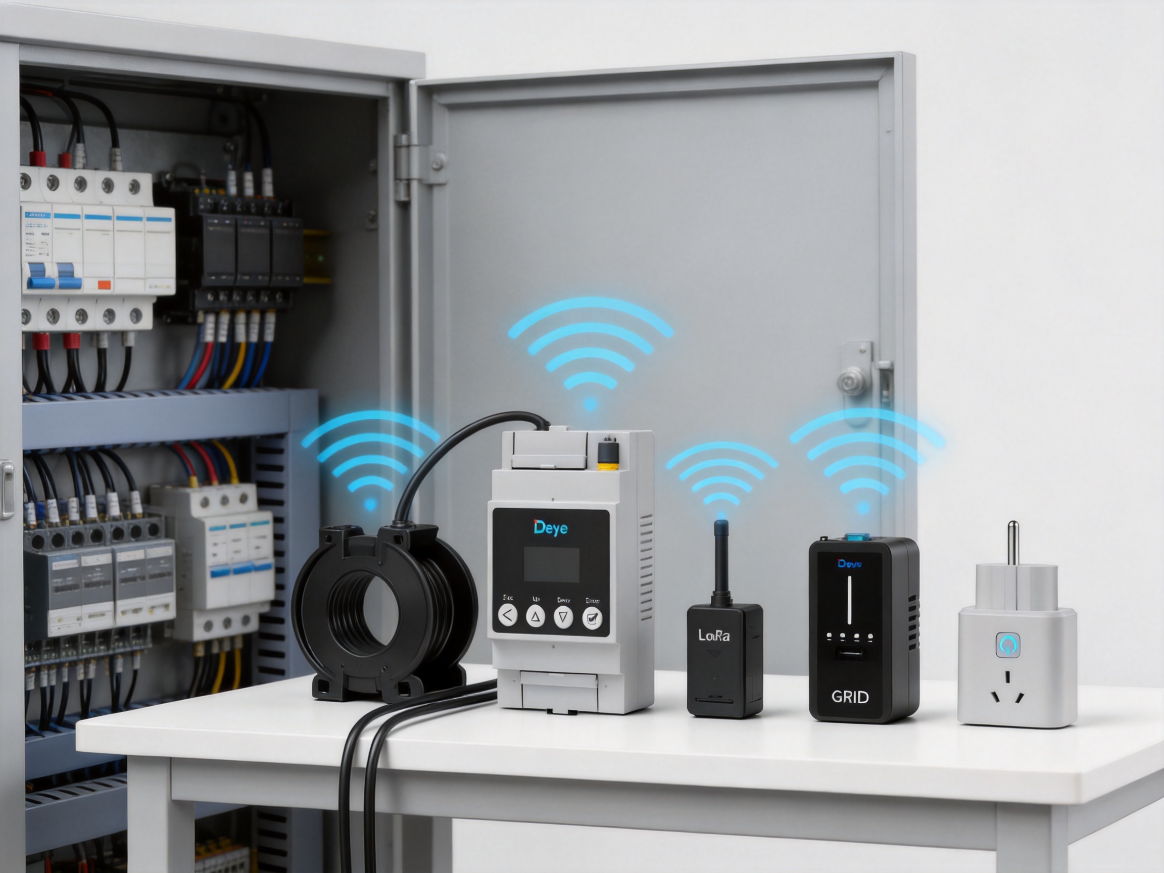
Professional installation is essential because the system interfaces with electrical circuits that may contain hazardous voltages and currents. The measurement unit, current transformers, switching equipment, and EV charger should be installed by qualified personnel who understand local wiring rules and protective requirements.
Before installation, the installer should identify the electrical phases, determine the point of measurement, confirm the expected current levels, and select suitable locations for wireless devices. The orientation and placement of current transformers should be verified carefully because incorrect installation can produce inaccurate readings or reverse the apparent direction of energy flow.
Wireless communication planning is also important. The specified range of approximately 200 meters applies to barrier-free conditions. Concrete walls, metal cabinets, reinforced structures, underground areas, and other obstructions can reduce communication performance. Devices should be positioned to provide the clearest practical path while remaining accessible for maintenance.
Commissioning should include verification of voltage, current, frequency, active power, and energy readings. The installer should compare displayed values with a trusted reference instrument where appropriate. Each smart switch, smart plug, transmitter, and EV charging unit should be paired and tested individually before complete automation rules are activated.
Load priorities should be documented clearly. Essential loads should not be assigned to a device that is intended to disconnect under normal energy-saving conditions. Similarly, the maximum current rating of each switch or plug must not be exceeded. Loads requiring dedicated protection, special starting currents, or continuous operation should be evaluated separately.
Recommended Commissioning Sequence
First, inspect the site and confirm that the selected components match the electrical system. This includes checking phase configuration, voltage, frequency, current capacity, enclosure conditions, and environmental temperature.
Second, install the CT01 in a suitable electrical cabinet and connect the measurement circuits in accordance with the product documentation. Verify that all protective devices, terminals, and conductors are correctly installed.
Third, power and pair the TX01 and associated wireless devices. Confirm communication quality at the intended operating locations before finalizing the mounting arrangement.
Fourth, connect the smart switch, smart plug, or EV charger to the intended load. Test local electrical operation and confirm that the device responds correctly to wireless commands.
Fifth, define load categories, SOC limits, schedules, and charging priorities. Begin with conservative settings and observe the system under different solar and consumption conditions.
Finally, provide the user with operating instructions, maintenance information, and a record of the configured rules. A well-documented installation is easier to troubleshoot and adapt in the future.
Maintenance and Long-Term Reliability
Wireless energy management equipment is designed to reduce day-to-day intervention, but periodic inspection remains advisable. Electrical connections should be checked according to local maintenance procedures. Enclosures should be inspected for damage, moisture, dust accumulation, or signs of overheating.
Measurement data can also help identify abnormal operating conditions. Unexpectedly high standby consumption, repeated switching, unstable communication, or unusual power readings may indicate an installation issue or a problem with the connected load.
The different warranty periods should be recorded by the installer or system owner. The CT01, smart switch, and smart plug have stated five-year warranties, while the TX01 has a stated two-year warranty. The EV charging equipment has its own product-specific warranty and service conditions.
Firmware, configuration, and communication settings should be managed in accordance with the manufacturer’s instructions. When a property is expanded with additional solar panels, batteries, EV chargers, or major loads, the energy management rules should be reviewed to ensure that they remain appropriate.
Environmental and Operational Performance
Energy management systems operate in environments that may experience seasonal temperature changes, variable humidity, and electrical disturbances. The product specifications address these conditions through defined operating temperature ranges, humidity limits, altitude ratings, and enclosure protection levels.
The CT01 and transmitter support operation from -40°C to +60°C, while the smart switch operates from -40°C to +45°C and the smart plug from -40°C to +60°C. The EV charging equipment operates from -40°C to +55°C. These ranges support many residential, commercial, and light industrial environments, provided that installation conditions remain within the specified limits.
IP ratings must be interpreted together with installation instructions. IP20 devices are generally intended for protected indoor locations, while IP65 and IP66 devices offer greater resistance to dust and water ingress when installed correctly. Even a high-rated enclosure should not be placed in an unsuitable environment without considering condensation, direct sunlight, chemical exposure, flooding, and ventilation.
Why an Integrated Ecosystem Matters
One of the main advantages of an integrated product ecosystem is reduced complexity. When the inverter, storage system, energy meter, wireless communication devices, load switches, and EV charger are designed to work together, the installer can use a more consistent approach to system architecture and troubleshooting.
Integration can also improve the quality of energy decisions. The system can use inverter and battery information alongside measured load data, allowing charging and switching rules to be coordinated rather than independently controlled by separate devices.
Another advantage is scalability. A small installation can begin with the measurement unit and one controlled load. As the customer’s energy needs grow, additional smart plugs, switches, or EV charging functions can be added without redesigning the entire system. This modular approach is suitable for households and businesses that want to improve energy performance in stages.
Compared with a collection of unrelated third-party products, a coordinated ecosystem can reduce compatibility risks. It may also simplify technical support because the installer has a clearer product family, consistent documentation, and a single primary manufacturer for core components.
Practical Energy Management Examples
Solar-Priority Electric Vehicle Charging
During midday, photovoltaic production may exceed household consumption. The system can use this surplus to charge an electric vehicle instead of exporting all excess energy. If clouds reduce solar output, charging can be reduced or paused, depending on the configured strategy.
The battery can be assigned a priority threshold. For example, EV charging may begin only after the battery reaches a selected SOC. This allows the homeowner to maintain a desired level of backup energy while still making use of surplus generation.
Water Heating and Appliance Control
A water heater or other flexible appliance can be connected through an appropriate smart switch. The system can enable the appliance during scheduled solar-production hours and disable it when energy availability falls below the selected threshold.
For plug-connected equipment within the rated current, the smart plug provides a simpler control method. This can be useful for selected appliances that do not require permanent wiring modifications.
Backup-Oriented Load Prioritization
In a property with battery backup, essential loads should be protected during periods of limited energy. Non-essential loads can be delayed or disconnected to extend battery runtime. The system’s load classification approach supports this type of priority-based operation, subject to the capabilities and configuration of the complete inverter and storage system.
Commercial Peak Reduction
A small business may use the system to prevent several flexible loads from operating at the same time. For example, EV charging, water heating, and selected workshop equipment can be scheduled or limited according to current site demand. This may reduce short-term peaks and make better use of onsite photovoltaic generation.
Q&A
What is the primary purpose of the wireless energy management system?
Its primary purpose is to measure energy conditions and control selected electrical loads so that solar power, battery energy, and grid electricity can be used more intelligently. It supports load prioritization, flexible scheduling, and charging strategies based on time and battery state of charge.
Can the system operate without an internet connection?
The system supports offline operation through local communication between its compatible components. This allows configured local control functions to continue when internet access is unavailable. Remote monitoring and application features may depend on the availability of the relevant network services.
What communication technology does the system use?
The main wireless communication technology is LoRa. The CT01 also supports RS485, and compatible EV charging equipment supports LoRa, Wi-Fi, and Bluetooth Low Energy. The stated LoRa communication distance is approximately 200 meters in barrier-free conditions.
Does it support single-phase and three-phase installations?
Yes. The CT01 supports L1/N single-phase connections and L1/L2/L3/N three-phase connections. The smart switch also supports single-phase and three-phase connection configurations. The exact installation must be selected according to the electrical design and local regulations.
What electrical information can the CT01 display?
The LCD can display voltage, current, active power, reactive power, frequency, power factor, and energy. The specified accuracy includes ±0.1 V for voltage, ±0.01 A for current, ±0.01 Hz for frequency, and ±1 W for power.
What is the difference between the smart switch and the smart plug?
The smart switch is intended for fixed electrical installation and supports up to 25 A AC phase current. The smart plug is a plug-type device rated for 220 to 250 V AC and up to 16 A AC. The correct choice depends on the load, connection method, current requirement, and installation environment.
Can the system control an electric vehicle charger?
Compatible AC EV charging equipment can participate in the energy management system. Available models support charging powers including 7 kW single-phase, 11 kW three-phase, and 22 kW three-phase configurations, depending on the model and electrical connection.
What charging methods are available for the EV charger?
The listed charging methods include plug-and-charge, charging after scanning, and scheduled charging. The charger also supports LoRa, Wi-Fi, and Bluetooth Low Energy communication.
How does SOC-based charging work?
SOC-based charging uses the battery’s state of charge as a control condition. For example, the system can reserve battery capacity until a selected SOC is reached before enabling another flexible load, such as an EV charger. This helps balance backup protection, solar self-consumption, and charging requirements.
Is the system suitable for new installations and retrofits?
It can be suitable for both, provided that the electrical system and compatible inverter meet the required conditions. Wireless communication may be particularly beneficial in retrofit projects because it can reduce the need for new communication cabling. A qualified installer should assess every site before selecting components.
What should be considered when planning wireless communication?
Communication range can be affected by walls, metal structures, reinforced concrete, underground locations, interference, and antenna placement. The approximately 200-meter range applies to barrier-free conditions. Devices should be positioned and tested during commissioning.
What environmental ratings are available?
The product family includes devices with IP20, IP65, and IP66 ratings. Operating temperature ranges extend as low as -40°C for several components. The appropriate device must be selected according to its intended location, and IP ratings must be supported by correct installation.
Who should install the system?
Electrical installation and commissioning should be performed by qualified professionals. The system includes devices connected to AC circuits, current transformers, switching equipment, and EV charging equipment. Local electrical codes, protective devices, conductor sizing, and safety procedures must be followed.
Conclusion
A wireless energy management system can transform a solar installation from a collection of generating and consuming devices into a coordinated energy platform. By combining accurate measurement, local control, LoRa communication, smart switching, plug-in load management, and managed EV charging, the system helps users make better use of available solar power.
Its main advantages over simpler monitoring or timer-based solutions are low-latency response, offline operation, long-range wireless communication, support for hybrid inverter systems, and flexible load prioritization. Time-based and SOC-based charging strategies provide additional control over batteries and electric vehicles, while single-phase and three-phase options support a wide range of installations.
The product family also reflects the strengths of an established manufacturer with experience in photovoltaic inverters, energy storage systems, microinverters, electrical control products, and energy IoT solutions. Integrated research and development, international product standards, defined environmental ratings, and a broad manufacturing portfolio provide a strong foundation for long-term deployment.
For homeowners, the system can increase solar self-consumption and simplify the management of appliances and EV charging. For small businesses, it can support load prioritization, peak management, and more effective use of onsite generation. With correct design, professional installation, and suitable configuration, it provides a scalable path toward safer, smarter, and more efficient energy use.
References
1. Product technical information for SUN-SMART-CT01 Wireless Energy Management System.
2. Product technical information for SUN-SMART-TX01 LoRa Wireless Transmitter.
3. Product technical information for SUN-SMART-SWITCH01P3 Smart Switch.
4. Product technical information for SUN-SMART-PLUG01-F Smart Plug.
5. Product technical information for SUN-EVSE11K01-EU-AC and SUN-EVSE22K01-EU-AC AC Electric Vehicle Chargers.
6. IEC/EN 61010-1, Safety requirements for electrical equipment for measurement, control, and laboratory use.
7. IEC/EN 62368-1, Audio/video, information and communication technology equipment safety requirements.
8. IEC 61851-1 and related standards for conductive charging systems for electric vehicles.
9. VDE 0620-2-1 and EN 61058, relevant standards for plug and switching equipment.
10. Manufacturer commissioning guidance for smart energy management devices and compatible hybrid inverter systems.
Product: Wireless energy management system
PREV:Three-Phase String Inverters for Efficient, Flexible, and Reliable Commercial Solar Systems
NEXT:High-Power Three-Phase String Inverter for Commercial and Industrial Solar Systems
Share
Product recommendations
news recommendations
-
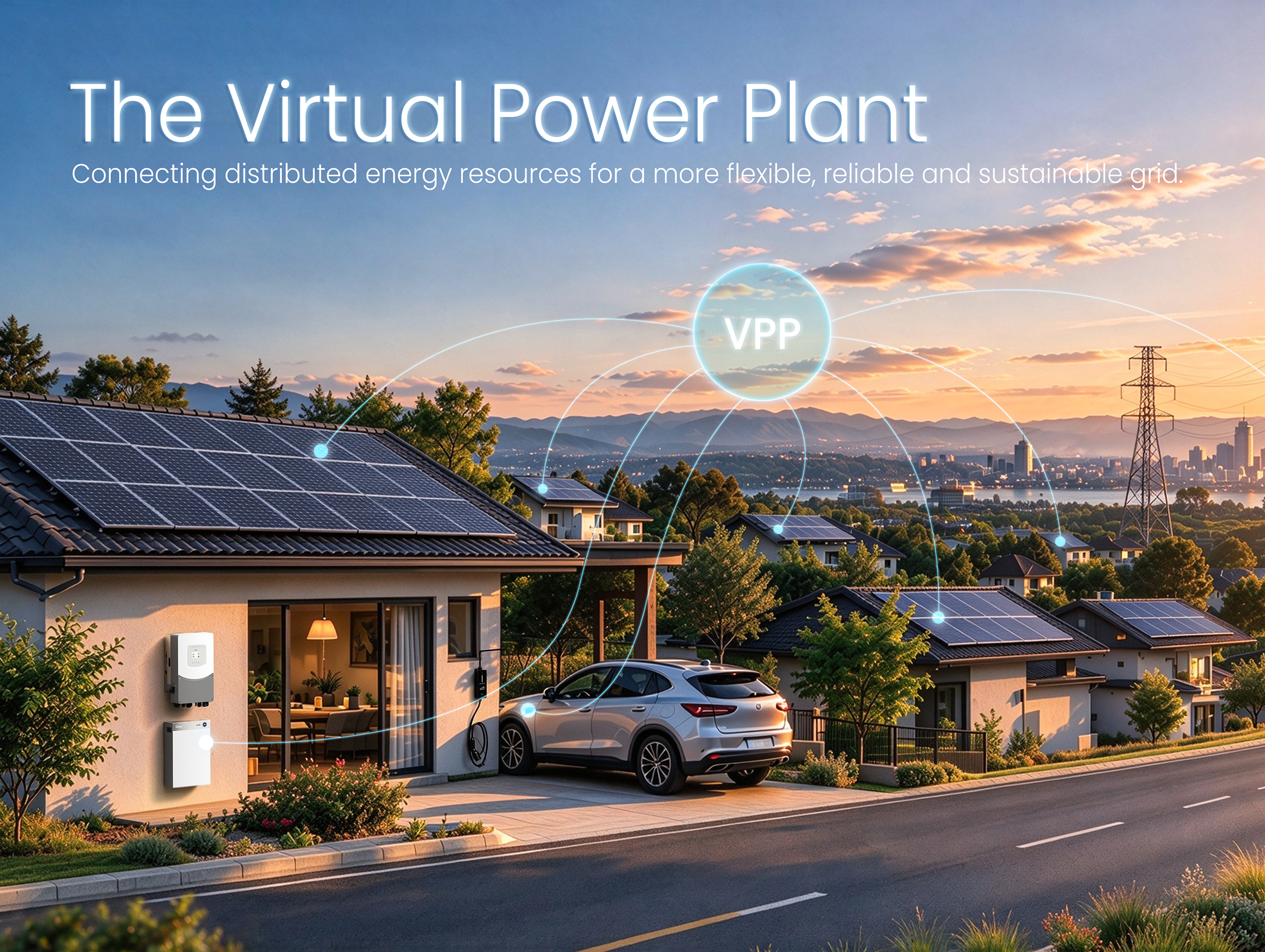 From Centralized Grids to Virtual Power Plants: The Next Evolution of the Power System
For more than a century, power systems around the world have relied on a centralized model. Large p...
-
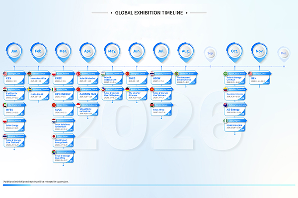 GLOBAL EXHIBITION TIMELINE
*Click to view larger image
-
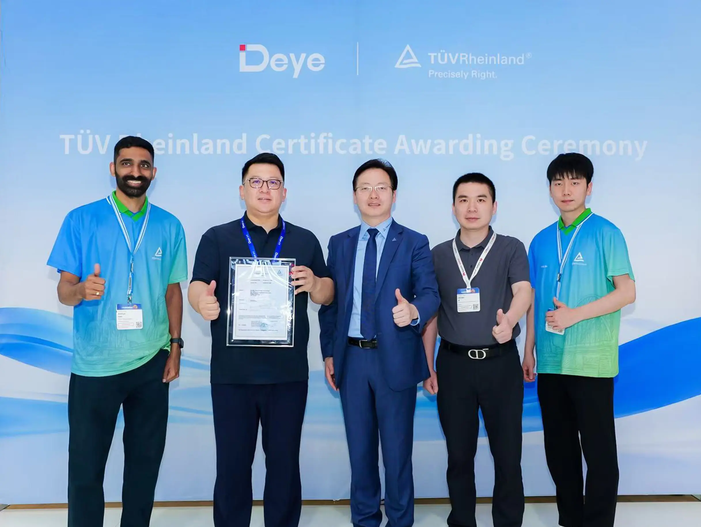 Deye Secures Multiple TÜV Rheinland Certifications at The smarter E Europe
On June 23, the opening day of The smarter E Europe 2026, Deye was officially awarded several presti...

Copyright@ 2024.Ningbo Deye Inverter Technology Co.,Ltd. All rights reserved. Solar Inverter Manufacturer
