
 Online Shop
 English
 China - 简体中文
 Global - English
 Brazil - Português
 Netherlands - Dutch
 Italy - Italiano
 Germany - Deutsch
 Spain - Español
 France - Français
 Vietnam - Tiếng Việt
 Poland - Polski
 Australia - English
 Japan - 日本語
Bai Shuying — After-Sales Support Supervisor, Solar Inverter Products

Four-MPPT Microinverters for High-Performance Single-Phase Solar Systems
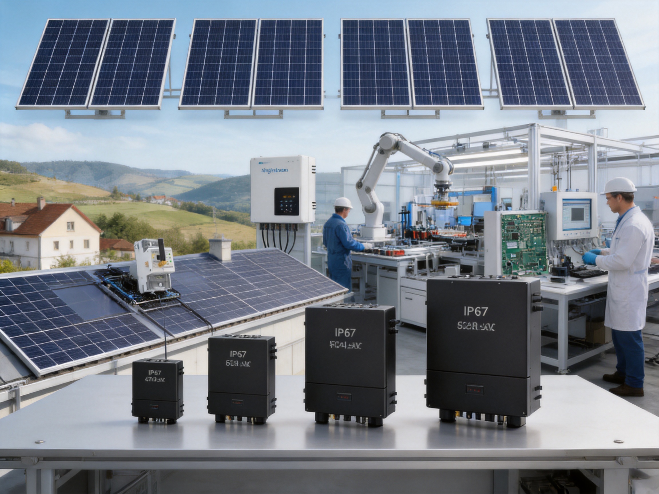
Microinverter technology has become an important part of modern distributed solar generation. Unlike a traditional string inverter, which manages power from a group of modules through one central conversion unit, a microinverter is installed at module level or across a small group of modules. This architecture can improve energy harvesting, simplify system design, and provide more detailed operating information for the owner and installer.
The SUN-M130/160/180/200/220G4-EU-Q0-I series is designed for single-phase photovoltaic systems requiring flexible module-level conversion in a compact format. The series includes five output ratings from 1,300 W to 2,200 W and provides four independent maximum power point trackers. It is intended for European grid applications and combines high input-current capability, module-level monitoring, rapid shutdown, wireless communication, IP67 protection, and a ten-year warranty.
This article examines the product architecture, electrical performance, installation value, protection functions, manufacturing strengths, and practical advantages of the series. It also explains which applications are most suitable for the product and answers common questions from installers, distributors, system designers, and end users.
Product Positioning and Series Overview
The SUN-M130/160/180/200/220G4-EU-Q0-I is a four-input, single-phase microinverter family. The model name identifies a group of closely related products rather than one single power rating. The available models are SUN-M130G4-EU-Q0-I, SUN-M160G4-EU-Q0-I, SUN-M180G4-EU-Q0-I, SUN-M200G4-EU-Q0-I, and SUN-M220G4-EU-Q0-I.
Every model supports four photovoltaic inputs, four MPP trackers, and one string per tracker. The principal difference between the models is their rated AC output power. This lets a system designer select an appropriate inverter according to the module rating, array size, local grid conditions, and desired DC-to-AC ratio.
| Model | Rated AC Output | Maximum PV Input Power | Maximum Units per Branch |
|---|---|---|---|
| SUN-M130G4-EU-Q0-I | 1,300 W | 210–460 W across four modules | 5 |
| SUN-M160G4-EU-Q0-I | 1,600 W | 210–560 W across four modules | 4 |
| SUN-M180G4-EU-Q0-I | 1,800 W | 210–630 W across four modules | 3 |
| SUN-M200G4-EU-Q0-I | 2,000 W | 210–700 W across four modules | 3 |
| SUN-M220G4-EU-Q0-I | 2,200 W | 210–770 W across four modules | 3 |
The listed photovoltaic input power ranges should be interpreted together with the electrical limits of the selected model, the module electrical characteristics, and the local installation requirements. The series has a maximum PV input voltage of 60 V, a startup voltage of 20 V, and an MPPT voltage range from 25 V to 55 V. These values make the product suitable for low-voltage module-level operation while requiring installers to verify the module voltage at the expected temperature extremes.
Four Independent MPP Trackers
One of the most important advantages of the series is its four independent MPP trackers. Each photovoltaic input has its own tracking channel, allowing the inverter to optimize the operating point of each connected module separately. The design is particularly valuable when modules experience different orientations, partial shading, dust accumulation, uneven aging, or small variations in electrical performance.
In a conventional string inverter, modules connected in the same string are influenced by the weakest operating conditions within that string. When one module is shaded or performs differently, the electrical behavior of the whole string can be affected. A four-MPPT microinverter reduces this type of interaction because each input is managed independently.
For residential rooftops, this flexibility can simplify array layout. Modules can be distributed across east-, south-, and west-facing roof sections without forcing every panel into one uniform string arrangement. Installers can also work around chimneys, skylights, parapets, dormers, and other sources of shading while maintaining independent energy optimization.
The product offers an MPPT efficiency greater than 99 percent. This figure refers to the effectiveness of the tracking process under specified operating conditions. Actual system energy yield will also depend on module quality, orientation, shading, temperature, wiring, grid availability, and installation workmanship. Nevertheless, the four-channel design creates a strong foundation for high energy capture in complex roof environments.
Compared with many entry-level microinverters that provide fewer tracking channels, the four-MPPT layout offers a meaningful system-design advantage. It allows one inverter to serve four modules while preserving independent control of each input. This can reduce the need for additional devices in arrays where module mismatch or roof complexity would otherwise limit the design.
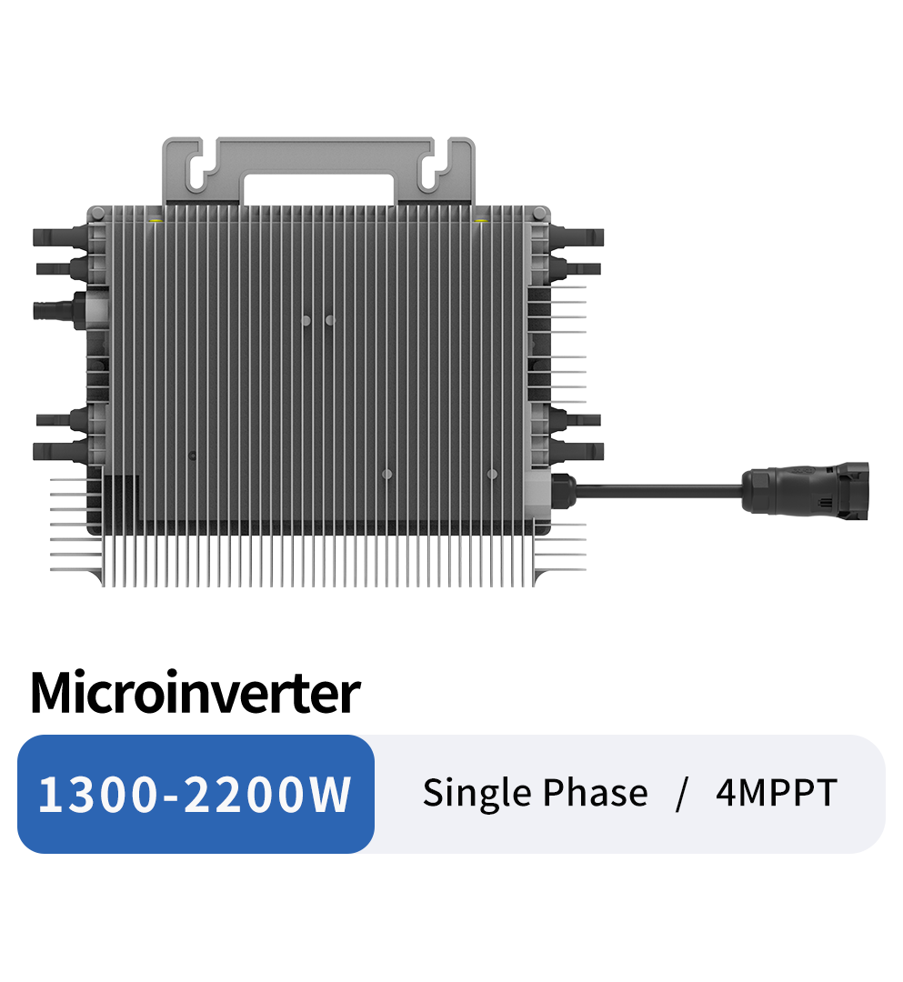
SUN-M130/160/180/200/220G4-EU-Q0-I
High-Current Input Capability for Modern PV Modules
Modern photovoltaic modules are becoming larger and more powerful. Many current-generation modules can deliver operating currents that exceed the input-current limits of older microinverter designs. If the inverter cannot accept the module’s current safely and effectively, the available module power may be restricted or the system designer may need to select a different device.
The SUN-M130/160/180/200/220G4-EU-Q0-I series provides a maximum operating PV input current of 18 A per input. The maximum input short-circuit current is 27 A per input. This specification allows the series to accommodate high-current modules, including modules with power ratings up to approximately 700 W under the relevant model and design conditions.
For the SUN-M200G4-EU-Q0-I, the stated maximum photovoltaic input power is 700 W across four modules, while the SUN-M220G4-EU-Q0-I reaches 770 W across four modules. Installers should always compare the module’s operating current, short-circuit current, voltage coefficient, and temperature-adjusted voltage with the inverter’s complete electrical specifications before final approval.
The high-current architecture is an advantage over microinverters designed around lower-current legacy modules. It gives distributors and installers greater freedom when selecting panels and helps protect the long-term relevance of the equipment as module technology develops. The product is not limited to older, lower-output panel formats simply because it is a microinverter.
High-current compatibility also supports cleaner product planning. A distributor can stock one modern microinverter family for a broad range of module products instead of maintaining separate low-current and high-current device categories. This can simplify purchasing, technical training, and service inventory.
Output Ratings and System Scalability
The five power ratings cover a wide range of single-phase applications. The smallest model provides 1,300 W of rated active power, while the largest provides 2,200 W. The available steps allow a system designer to match the inverter more closely to the intended module configuration.
The rated AC output power and maximum AC apparent power are the same for each model. Rated output current ranges from 6 A or 5.7 A for the 1,300 W model to 10 A or 9.6 A for the 2,200 W model, depending on the applicable nominal voltage condition. This range gives the installer clear information for branch-circuit design and protective-device selection.
The maximum number of units per branch varies according to the selected model. Up to five SUN-M130G4-EU-Q0-I units may be used on one branch under the stated product data. Four SUN-M160G4 units may be used, while the higher-output models are limited to three units per branch. These limits should be followed together with applicable electrical codes, conductor ratings, ambient-temperature derating, and local grid requirements.
| Electrical Characteristic | Product Range or Value |
|---|---|
| Number of MPP trackers | 4 |
| Strings per MPP tracker | 1 |
| Maximum PV input voltage | 60 V |
| Startup voltage | 20 V |
| MPPT voltage range | 25–55 V |
| Maximum operating input current | 18 A per input |
| Maximum short-circuit current | 27 A per input |
| Rated AC voltage | 220/230 V |
| Grid connection | L/N/PE |
| Grid frequency | 50 Hz or 60 Hz, according to the applicable range |
| Maximum efficiency | 96.50% |
| MPPT efficiency | Greater than 99% |
The modular nature of a microinverter system also supports phased installation. A homeowner may initially install a limited number of panels and add additional units later, provided that the AC branch, protection, structural capacity, grid connection, and monitoring plan are designed for expansion. This is more flexible than replacing a central inverter when a small system expansion exceeds the original inverter capacity.
Energy Harvesting in Difficult Rooftop Conditions
Rooftops are rarely perfect rectangles with identical solar exposure. Trees, neighboring buildings, antennas, vents, roof ridges, and seasonal shadows can create significant differences between modules. The four-MPPT design is intended to reduce the impact of such differences at the conversion stage.
When one module is shaded, the other connected modules can continue operating at their own optimum points. When one roof face receives morning sunlight and another receives afternoon sunlight, each input can follow its own changing current-voltage curve. This can improve the practical energy yield compared with a uniform string arrangement in which all modules are forced to share a common operating point.
The product is not a substitute for proper site assessment. Good system design still requires shade analysis, appropriate module placement, correct cable routing, and consideration of ventilation and temperature. However, the product architecture gives the designer more tools for handling unavoidable roof complexity.
Module-level conversion can also help identify underperforming panels. If a single module develops a fault or suffers from abnormal shading, its behavior can be examined without assuming that the entire array is defective. This can shorten troubleshooting time and reduce unnecessary service visits.
Module-Level Monitoring and Wireless Communication
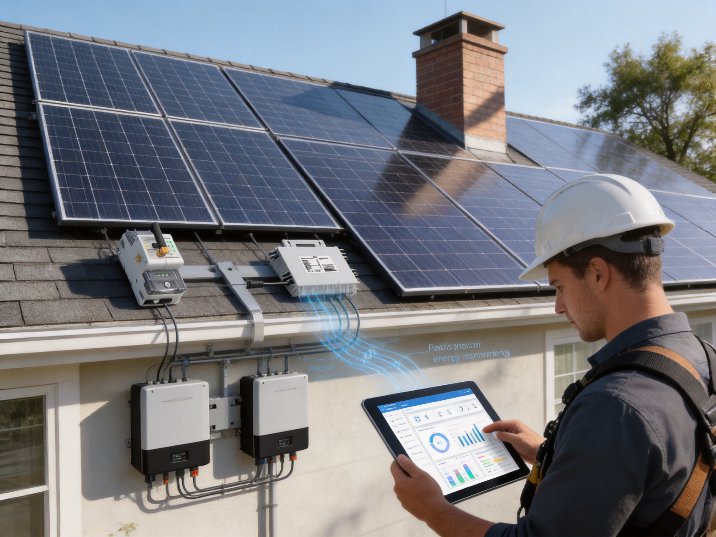
The series supports module-level monitoring through wireless Wi-Fi communication. The wireless approach reduces the need for additional communication wiring between individual microinverters, which can simplify installation and reduce cable congestion beneath the modules.
Monitoring is valuable for both system owners and professional operators. A homeowner can observe production trends and detect unexpected changes. An installer or service team can use operating information to distinguish between a module problem, a microinverter problem, a branch-circuit issue, or a grid event.
Module-level data also supports more transparent system performance analysis. Instead of seeing only the total output of an entire string, the operator can compare individual module channels. This is particularly useful in arrays with multiple orientations or known shading differences.
Wireless communication should not be treated as an unlimited replacement for sound network planning. The installer must evaluate the communication environment, signal strength, device placement, interference, and monitoring gateway requirements. In a large or physically complex installation, the wireless network should be checked during commissioning and after the system is fully assembled.
Compared with wired monitoring architectures, wireless communication can provide a faster installation process and fewer low-voltage cables. This is one of the product’s practical advantages over systems that require extensive communication wiring. It also makes retrofit work less disruptive when the roof or building has limited access for new cables.
Bidirectional Measurement and Export Control
The product information identifies bidirectional measurement as a key function. This function can record electricity consumption data while also helping prevent energy backflow to the grid. Such capability is important in locations where the system owner wants to maximize self-consumption or where the utility connection has export limitations.
Bidirectional measurement provides a more complete view of the relationship between generation, household consumption, and grid exchange. During periods of high solar production and low local demand, the system can identify the direction and amount of power flow. During periods of low solar production, it can record energy imported from the grid.
Export control must be designed and commissioned in accordance with the applicable local regulations and the complete system architecture. Meter placement, communication, phase configuration, response time, and backup behavior should be checked by qualified personnel. The microinverter’s stated function does not eliminate the need for a correctly installed meter and compatible control equipment.
For residential and small commercial users, this function can improve the economic value of solar generation. More energy can be consumed on site, while unwanted export can be limited where required. It also supports better energy management when combined with batteries, electric vehicle charging, heat pumps, or other controllable loads.
Rapid Shutdown and Electrical Safety
Rapid shutdown is an important safety function for photovoltaic installations. During an emergency, maintenance activity, or fire response, reducing energized DC conductors on the roof can help improve the safety conditions for authorized personnel.
Because the series performs power conversion close to the modules, it can support a system architecture with shorter high-voltage DC paths than a conventional string inverter. The listed rapid shutdown function adds another layer of safety design, although the complete installation must still use compatible equipment and follow the requirements of the local authority having jurisdiction.
The product includes several additional protection functions. These include DC reverse-polarity protection, AC output overcurrent protection, AC output overvoltage protection, AC short-circuit protection, thermal protection, insulation impedance detection, and anti-islanding protection.
| Protection or Safety Function | Availability | Practical Benefit |
|---|---|---|
| DC reverse-polarity protection | Yes | Helps protect the input stage from incorrect DC connection polarity |
| AC overcurrent protection | Yes | Supports protection against excessive output current |
| AC overvoltage protection | Yes | Helps respond to abnormal AC voltage conditions |
| AC short-circuit protection | Yes | Provides protection during output-side fault conditions |
| Thermal protection | Yes | Helps manage abnormal temperature conditions |
| Insulation impedance detection | Yes | Supports identification of insulation-related problems |
| Anti-islanding protection | Yes | Helps prevent continued energization of an isolated utility circuit |
| Rapid shutdown | Supported | Contributes to emergency and maintenance safety procedures |
The inverter also specifies Type II AC surge protection and overvoltage categories of OVC II on the DC side and OVC III on the AC side. Surge protection is only one part of a complete installation. External protection, grounding, bonding, lightning protection, and cable routing must be designed according to the site risk assessment and governing standards.
Grid Compatibility and Power Quality
The product is designed for single-phase grid connection through L/N/PE conductors. It supports nominal output voltage of 220 V or 230 V, with an output voltage range expressed as 0.85 Un to 1.1 Un. The rated frequency can be 50 Hz or 60 Hz, with the stated frequency ranges of 45–55 Hz and 55–65 Hz.
The series supports a power-factor adjustment range from 0.9 leading to 0.9 lagging. This gives system designers flexibility where the grid operator requires reactive-power control or a specified power-factor operating range.
Total current harmonic distortion is specified at less than 3 percent, and DC injection current is specified at less than 0.5 percent of rated current. Lower distortion helps support better power quality and can simplify compliance with applicable grid-connection rules, although the complete installation must be assessed as a system rather than by inverter specifications alone.
The listed grid regulations include IEC 61727, IEC 62116, CEI 0-21, EN 50549, NRS 097, RD 140, UNE 217002, G98, and VDE-AR-N 4105. The series also lists safety and electromagnetic compatibility standards including IEC/EN 61000-6-1, IEC/EN 61000-6-2, IEC/EN 61000-6-3, IEC/EN 61000-6-4, IEC/EN 62109-1, and IEC/EN 62109-2.
Certification and grid approval requirements vary by country and by exact model revision. Installers should confirm the current approval documentation before proposing the product for a specific market. This is especially important when a utility requires a particular national certificate, protection setting, or commissioning procedure.
Efficiency and Thermal Design
The maximum efficiency of the series is listed as 96.50 percent, with a Euro efficiency value of 96 and MPPT efficiency greater than 99 percent. Maximum efficiency is normally achieved under favorable operating conditions, while Euro efficiency provides a weighted value intended to represent a broader operating profile.
Efficiency affects annual energy production, heat generation, and the overall utilization of available roof area. A small difference in conversion loss can become meaningful over many years of operation, especially in systems with high annual irradiation and large energy throughput.
The inverter uses natural cooling rather than a fan-based cooling system. Natural cooling can offer several practical benefits: fewer moving parts, lower acoustic output, and reduced mechanical complexity. The listed noise level is no more than 25 dB, making the unit suitable for residential environments where equipment noise is a concern.
Natural cooling does not mean that installation location is unimportant. The product must be mounted according to the manufacturer’s instructions, with sufficient clearance and without unnecessary exposure to heat accumulation. Ventilation around the equipment should be maintained, and the unit should not be covered by insulation, debris, or materials that obstruct heat dissipation.
The operating temperature range is specified from -40°C to +65°C, with permissible ambient humidity from 0 to 100 percent. These figures indicate a broad environmental operating capability, but the installer should still consider solar radiation, mounting position, wind exposure, salt spray, snow, condensation, and local environmental contaminants.
Durable Enclosure and Compact Installation
The series has an IP67 ingress protection rating. This provides strong protection against dust ingress and temporary water immersion under defined test conditions. IP67 is well suited to equipment installed beneath photovoltaic modules, where the inverter may be exposed to rain, dust, condensation, and changing outdoor temperatures.
The cabinet size is 311 × 250.5 × 36.5 millimeters, excluding connectors and brackets, and the stated weight is 4.95 kilograms. The compact profile helps reduce visual impact and can make handling easier during rooftop work. A relatively slim device also supports installation in locations where space beneath the module frame is limited.
Although the enclosure is compact, installers must respect the specified mounting orientation, cable bend radius, connector clearances, and spacing requirements. Waterproof connectors should be fully engaged, unused inputs should be protected correctly, and the AC trunk system should be assembled with compatible components.
The ten-year warranty provides an additional ownership benefit. Warranty coverage is subject to the manufacturer’s terms, registration requirements, installation conditions, and applicable service procedures. Buyers should retain invoices, commissioning records, serial numbers, and maintenance documentation throughout the operating life of the system.
Advantages Compared with Conventional String Inverters
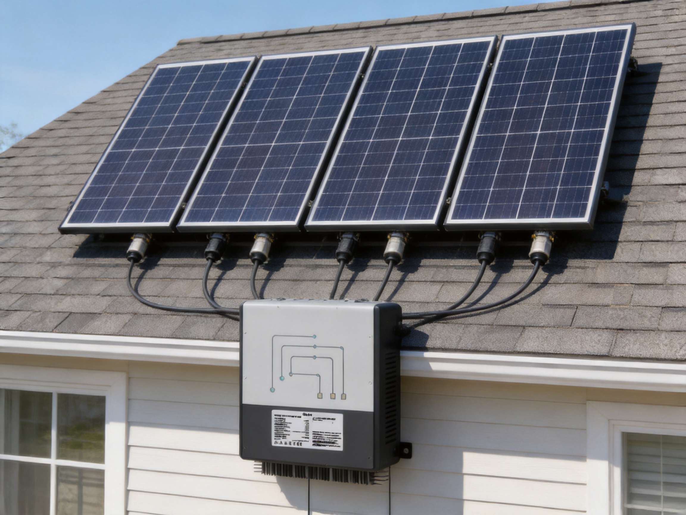
The strongest comparison between this microinverter series and conventional string inverters concerns system architecture. A string inverter normally aggregates several modules into one or more high-voltage DC strings. The microinverter instead converts module-level DC power into AC close to the panels.
This can reduce the length of high-voltage DC wiring and may simplify rooftop safety planning. It also makes the system less dependent on one central conversion unit. If a string inverter fails, a large portion of the array may stop producing. In a microinverter system, a localized device issue generally affects only the connected module group, while the remaining units can continue operating.
The four independent MPP trackers are another important distinction. String inverters may offer multiple trackers, but the number of trackers is often lower than the number of connected modules. The product’s four-input structure provides fine-grained optimization without requiring one separate device for every panel.
Microinverter architecture also simplifies expansion in many residential situations. Additional panels can be added by installing additional microinverters, subject to branch limits and electrical approval. A central inverter system may require a larger replacement inverter or a more complicated redesign if future expansion exceeds the original capacity.
On the other hand, string inverters can remain attractive for large, uniform arrays with limited shading and straightforward roof geometry. The best choice depends on project size, installation labor, equipment location, service strategy, and local regulations. The value of the SUN-M series is particularly clear where module mismatch, roof complexity, safety requirements, and detailed monitoring are important.
Advantages Compared with Lower-Specification Microinverters
Not all microinverters offer the same number of MPPT channels or the same current-handling capability. The four-MPPT configuration allows the SUN-M series to connect four modules with independent tracking. This can be more flexible than a two-MPPT design when a roof has multiple orientations or partial shading.
The 18 A maximum operating current per input is also significant. Some older or entry-level microinverters are designed around lower-current modules and may not be fully compatible with the newest high-power panels. The SUN-M series is positioned for the continuing trend toward higher-output modules.
The product also combines wireless communication, rapid shutdown, bidirectional measurement, IP67 protection, natural cooling, and a ten-year warranty. A competing microinverter may offer one or two of these functions but not necessarily all of them in the same compact platform.
The five available power ratings are another advantage for channel partners. A product family that extends from 1,300 W to 2,200 W can cover a broader range of projects while maintaining common installation concepts, monitoring methods, and service procedures.
Manufacturing Strengths and Product Development Capability
Ningbo Deye Inverter Technology Co., Ltd. is described as a comprehensive technology manufacturing enterprise integrating research and development, design, production, sales, and service. This vertically coordinated structure is important in the inverter industry because product reliability depends on cooperation between electrical design, embedded software, mechanical engineering, production control, testing, logistics, and after-sales support.
The company was founded in 2000 and was listed on the Shanghai Stock Exchange in April 2021. Its stated business covers photovoltaic inverters, energy storage systems, dehumidifiers, and HVAC products. This breadth gives the organization experience across power electronics, thermal management, environmental equipment, and energy-related products.
The company’s inverter and energy-storage businesses have developed R&D capabilities and manufacturing scale across residential, commercial, industrial, and utility applications. Its product portfolio includes string inverters from 1 kW to 136 kW, energy-storage inverters from 3 kW to 80 kW, and microinverters from 300 W to 2.2 kW.
That product range is relevant to the SUN-M series because it indicates a broad understanding of different PV system architectures. A manufacturer that develops microinverters, string inverters, hybrid inverters, and energy-storage products can address the changing needs of installers who want to combine solar generation with batteries, electric vehicles, and intelligent energy management.
Advanced manufacturing should be evaluated not only by factory automation but also by the consistency of the complete product-development process. For a microinverter, important areas include component selection, printed circuit board assembly, power-stage design, insulation control, enclosure sealing, connector quality, software validation, thermal testing, electromagnetic compatibility, and end-of-line inspection.
The listed safety and EMC standards demonstrate that the product is developed for demanding electrical and regulatory environments. Compliance with these standards requires controlled design practices and documented testing. The stated IP67 rating, wide operating-temperature range, low noise, and protection functions further indicate that the product is engineered for outdoor power conversion rather than light indoor use.
Manufacturing strength also includes the ability to support product availability and service over time. A global sales presence covering more than 140 countries and regions gives the company experience with differing grid rules, installation practices, climate conditions, and customer requirements. This international exposure can support continuous product refinement and more effective technical documentation.
The company’s Deye Cloud App and broader energy IoT ecosystem add another layer to its manufacturing and technology strengths. Hardware, communication, monitoring software, and service tools increasingly need to work as one system. The SUN-M series benefits from being part of a wider platform rather than an isolated hardware product.
Quality Considerations for Installers and Distributors
Product quality is not determined by the nameplate rating alone. Installers should review the exact model, firmware version, connector type, grid certificate, branch limits, communication accessories, and installation manual before delivery. The datasheet provides the main electrical and environmental characteristics, while project documentation determines how the device should be installed and commissioned.
Distributors should also confirm packaging protection, serial-number traceability, warranty registration, replacement procedures, and technical support channels. Because microinverters are distributed across a roof, service planning should include access strategy and the availability of compatible replacement units.
During installation, every connector should be inspected for damage, correct polarity, complete locking, and proper sealing. AC trunk connections should be protected from mechanical stress, and cable management should prevent contact with sharp edges or areas of standing water. The equipment should be mounted firmly and positioned to maintain cooling and drainage.
Commissioning should include verification of the grid voltage, frequency, phase connection, grounding, communication link, module identity, and monitoring data. The installer should confirm that each module channel reports correctly and that bidirectional measurement or export-control functions operate as intended.
Recommended Applications
The SUN-M130/160/180/200/220G4-EU-Q0-I series is well suited to residential rooftop systems, small commercial buildings, villas, multi-orientation roofs, and installations where module-level monitoring is valuable.
It is particularly appropriate for roofs with partial shading or several roof planes. The four independent trackers can help the system maintain better operating flexibility than a single-string arrangement. The compact enclosure and low noise are also favorable for homes where the equipment is installed close to occupied spaces.
The series can support new construction and retrofit projects. In a new installation, the designer can plan the AC branch layout and monitoring system from the beginning. In a retrofit, wireless communication may reduce the need to install additional communication cables through finished building areas.
The product can also be considered for solar systems that may later add batteries, electric vehicle charging, or controllable loads. The inverter itself is a grid-tied microinverter, so the complete future architecture must be reviewed carefully. Adding storage or backup capability may require separate compatible equipment and should not be assumed solely from the presence of bidirectional measurement.
Installation Planning Checklist
Before installation, confirm that the selected module’s maximum power, operating current, short-circuit current, open-circuit voltage, and temperature coefficients fall within the inverter limits. Check the maximum PV voltage at the lowest expected temperature, not only the module’s standard test condition voltage.
Confirm the number of microinverters permitted on each AC branch. The branch limit is model-dependent: five units for the 1,300 W model, four for the 1,600 W model, and three for the 1,800 W, 2,000 W, and 2,200 W models according to the supplied specifications.
Review local grid requirements and select the correct country or regional setting. Verify whether the project requires a specific certificate, external meter, export-control device, surge-protection arrangement, residual-current protection method, or utility inspection.
Plan the wireless communication path before mounting the modules. Metal roofing, reinforced concrete, inverters installed in enclosed spaces, and other radio obstacles can affect signal quality. Complete monitoring commissioning only after all units are installed and powered in the intended final arrangement.
Finally, provide the owner with documentation covering system operation, monitoring access, warranty information, emergency procedures, and maintenance recommendations. Clear handover information helps preserve the value of module-level monitoring and supports faster troubleshooting throughout the system life.
Frequently Asked Questions
What type of inverter is the SUN-M130/160/180/200/220G4-EU-Q0-I?
It is a single-phase grid-connected microinverter series for photovoltaic systems. The series includes five rated AC output levels from 1,300 W to 2,200 W and provides four independent photovoltaic inputs with four MPP trackers.
How many solar modules can one unit connect?
The inverter provides four photovoltaic inputs and one string per MPP tracker. It is designed around a four-module configuration, subject to module electrical characteristics, the selected model, and the installation instructions.
Can it work with high-power solar panels?
Yes. The maximum operating PV input current is 18 A per input, and the maximum input short-circuit current is 27 A per input. The series is designed to accommodate modern high-current modules, including module ratings up to approximately 700 W under the applicable model conditions. Compatibility must be verified using the exact module datasheet.
What is the main benefit of four MPPTs?
Four MPPTs allow the four inputs to operate independently. This is useful when modules have different orientations, partial shading, dust levels, or performance characteristics. It can reduce the energy impact of mismatch compared with a system in which several modules share one tracking channel.
Does the product support module-level monitoring?
Yes. The product supports module-level monitoring through wireless Wi-Fi communication. Monitoring can help owners and installers review production and identify underperforming channels.
Does it support rapid shutdown?
Yes. Rapid shutdown is listed as one of the product functions. The complete system must use compatible equipment and follow the applicable local emergency and electrical-safety requirements.
What protection functions are included?
The listed functions include DC reverse-polarity protection, AC output overcurrent protection, AC output overvoltage protection, AC short-circuit protection, thermal protection, insulation impedance detection, anti-islanding protection, and Type II AC surge protection.
What is the enclosure protection rating?
The enclosure is rated IP67. This rating provides protection against dust ingress and temporary immersion under defined test conditions. Correct connector assembly and installation remain essential for achieving the intended outdoor protection.
How does the inverter cool itself?
The product uses natural cooling. It has a listed noise level of no more than 25 dB and does not rely on a fan-based cooling system. Adequate mounting clearance and unobstructed heat dissipation are still required.
What is the warranty period?
The supplied product information lists a ten-year warranty. The applicable terms, registration process, exclusions, and service conditions should be confirmed in the current warranty documentation.
Can the inverter prevent unwanted export to the grid?
The product information identifies bidirectional measurement that can record consumption data while also helping prevent backflow. Export-control performance depends on correct meter installation, communication, configuration, local regulations, and the complete system design.
Is the inverter suitable for every European country?
The series lists multiple European and international grid regulations, including EN 50549, CEI 0-21, G98, and VDE-AR-N 4105. However, approval requirements differ by country, utility, model, and firmware version. The installer must verify the exact current certification before deployment.
What should be checked before connecting a module?
Check the module’s maximum power, operating current, short-circuit current, open-circuit voltage, and temperature-adjusted voltage. These values must remain within the inverter’s specified limits under all expected operating conditions.
Is this product better than a string inverter?
It can be advantageous where the roof has shading, multiple orientations, module mismatch, limited space for a central inverter, or a strong need for module-level monitoring. A string inverter may remain more economical for large, uniform arrays. The correct choice depends on the project design and local installation conditions.
Conclusion
The SUN-M130/160/180/200/220G4-EU-Q0-I series combines the principal advantages of module-level power conversion with a high-current input design suited to modern photovoltaic modules. Its four independent MPP trackers provide flexibility for complex rooftops, while the five output ratings allow close matching to different array sizes.
The product’s 18 A input-current capability, rapid shutdown function, wireless monitoring, bidirectional measurement, IP67 enclosure, natural cooling, broad temperature range, and ten-year warranty create a well-rounded platform for single-phase solar systems.
Compared with conventional string-inverter designs, the series offers finer energy optimization, localized conversion, module-level visibility, and potentially simpler expansion. Compared with lower-specification microinverters, it provides four tracking channels and higher current compatibility in a compact family.
These product strengths are supported by the manufacturer’s integrated R&D, design, production, sales, and service structure; broad inverter and energy-storage portfolio; international market experience; and energy IoT ecosystem. For installers and distributors, the result is a scalable product family that can address residential and small commercial requirements while remaining adaptable to the continued development of photovoltaic module technology.
References
Deye, SUN-M130/160/180/200/220G4-EU-Q0-I Product Datasheet, technical edition supplied for this article.
Deye, SUN-M130/160/180/200G4-EU-Q0-I Installation and Operation Manual, technical edition supplied for this article.
IEC 61727, Photovoltaic Systems—Utility Interface Characteristics.
IEC 62116, Utility-Interconnected Photovoltaic Inverters—Test Procedure of Islanding Prevention Measures.
IEC/EN 62109-1, Safety of Power Converters for Use in Photovoltaic Power Systems—General Requirements.
IEC/EN 62109-2, Safety of Power Converters for Use in Photovoltaic Power Systems—Particular Requirements for Inverters.
EN 50549, Requirements for the Connection of Generators in Parallel with Public Distribution Networks.
VDE-AR-N 4105, Power Generating Plants on the Low-Voltage Grid.
Applicable national electrical installation codes, utility interconnection rules, rapid-shutdown requirements, and photovoltaic system commissioning procedures.
Product: SUN-M130/160/180/200/220G4-EU-Q0-I
PREV:High-Performance Three-Phase String Inverters for Commercial Solar Plants
NEXT:Smart Solar-Integrated EV Charging for Homes and Energy-Savvy Businesses
Share
Product recommendations
news recommendations
-
 From Centralized Grids to Virtual Power Plants: The Next Evolution of the Power System
For more than a century, power systems around the world have relied on a centralized model. Large p...
-
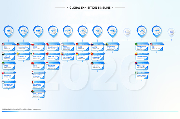 GLOBAL EXHIBITION TIMELINE
*Click to view larger image
-
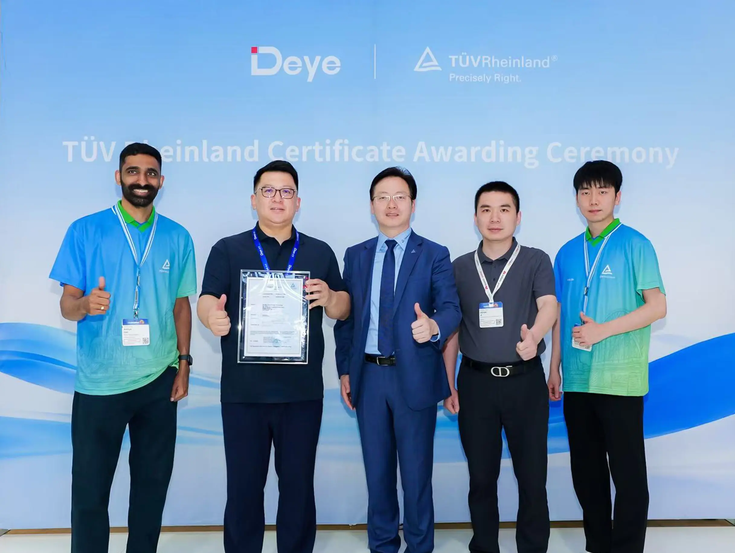 Deye Secures Multiple TÜV Rheinland Certifications at The smarter E Europe
On June 23, the opening day of The smarter E Europe 2026, Deye was officially awarded several presti...

Copyright@ 2024.Ningbo Deye Inverter Technology Co.,Ltd. All rights reserved. Solar Inverter Manufacturer
