
 Online Shop
 English
 China - 简体中文
 Global - English
 Brazil - Português
 Netherlands - Dutch
 Italy - Italiano
 Germany - Deutsch
 Spain - Español
 France - Français
 Vietnam - Tiếng Việt
 Poland - Polski
 Australia - English
 Japan - 日本語

Zhuo Yiran — Senior After-Sales Service Engineer, Energy Storage Systems

High-Efficiency Three-Phase String Inverters for Modern Commercial Solar Systems
As photovoltaic installations become larger, more distributed, and more closely integrated with intelligent energy management, the quality of the inverter has become just as important as the performance of the solar modules. A three-phase string inverter must do more than convert direct current into usable alternating current. It must optimize energy harvest, comply with grid requirements, protect connected equipment, support remote monitoring, operate reliably under changing environmental conditions, and provide installers with a practical balance between performance, cost, and simplicity.
The SUN-(3-15)K-G06P3-EU-BM2-P1 series is designed to address these requirements in commercial, agricultural, light-industrial, and larger residential photovoltaic applications. Covering rated power levels from 3 kW to 15 kW, the series provides a flexible platform for three-phase grid-connected solar systems. Its central technical characteristics include two maximum power point trackers, a maximum efficiency of up to 98.5%, a wide photovoltaic operating voltage range, support for zero-export applications, optional intelligent string monitoring, and compatibility with several grid regulations used across Europe and other international markets.
Rather than relying on a single configuration for every installation, the product family offers ten power classes: 3 kW, 4 kW, 5 kW, 6 kW, 7 kW, 8 kW, 9 kW, 10 kW, 12 kW, and 15 kW. This range enables system designers to select an inverter that more closely matches the available roof area, module capacity, electrical load, and local interconnection requirements. The result can be a more balanced photovoltaic system, avoiding unnecessary oversizing while leaving room for appropriate DC oversizing on the solar array.
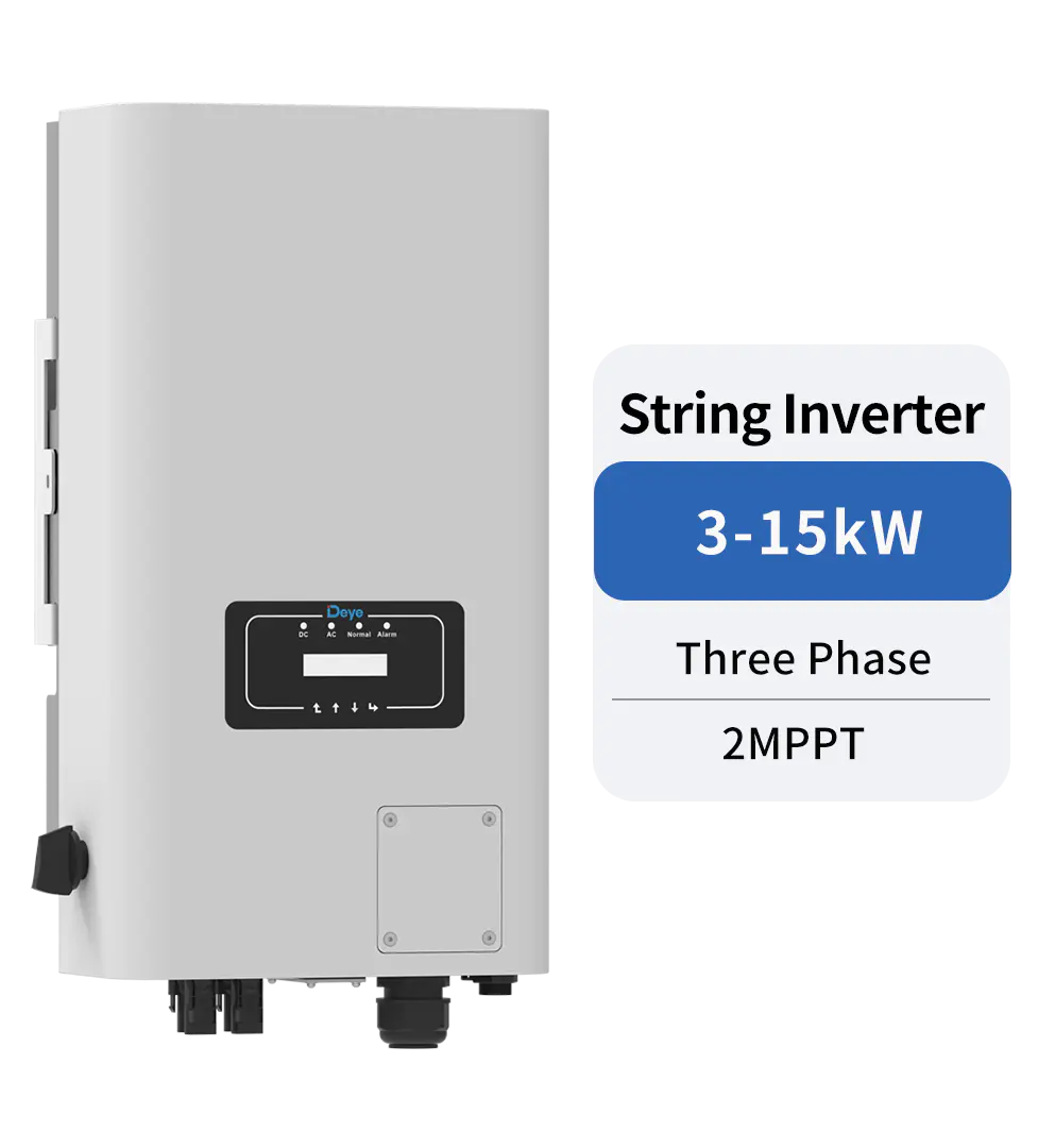
SUN-3/4/5/6/7/8/9/10/12/15K-G06P3-EU-BM2-P1
Product Overview and Application Positioning
The inverter series belongs to the three-phase string inverter category. In a string architecture, solar modules are connected in series to create photovoltaic strings, and those strings are connected to the inverter’s DC inputs. The inverter tracks the operating point of the strings, converts DC electricity into synchronized three-phase AC power, and exports that electricity to the local loads or utility grid.
Three-phase string inverters are particularly suitable for buildings and sites with three-phase electrical infrastructure. Typical applications include workshops, warehouses, farms, office buildings, retail premises, schools, small factories, multi-unit buildings, and commercial rooftops. They can also be used in larger residential systems where a three-phase grid connection is available.
The series supports AC grid configurations based on 3L/N/PE wiring. It is compatible with nominal output systems of 220/380 V and 230/400 V, with an operating voltage range of 0.85 to 1.1 times the nominal voltage. This allows the inverter to serve a broad range of European-style low-voltage three-phase applications, subject to local approval and installation requirements.
With models ranging from 3 kW to 15 kW, the platform can be used for both small and medium-sized systems. A 3 kW model may be appropriate for a small commercial roof or a three-phase home, while a 15 kW model can support a substantially larger array and higher daytime consumption. Multiple units can also be considered in larger installations, provided that the system design, protection, communication, and grid connection requirements are properly coordinated.
Key product characteristics
The main product characteristics are summarized below:
| Item | Specification |
|---|---|
| Product family | SUN-(3-15)K-G06P3-EU-BM2-P1 |
| Rated power range | 3 kW to 15 kW |
| Phase configuration | Three-phase |
| MPP trackers | 2 |
| Maximum PV input voltage | 1100 V |
| MPPT voltage range | 120 V to 1000 V |
| Start-up voltage | 140 V |
| Maximum efficiency | Up to 98.5% |
| Maximum PV input power | 4.5 kW to 22.5 kW, depending on model |
| AC grid connection | 3L/N/PE |
| Power factor adjustment | 0.8 leading to 0.8 lagging |
| Total current harmonic distortion | Less than 3% |
| Ingress protection | IP65 |
| Cooling method | Natural cooling |
| Communication interfaces | RS485 and RS232 |
| Optional monitoring | GPRS, Wi-Fi, Bluetooth, 4G, and LAN |
| Warranty | 5 years |
Two MPPT Architecture for Flexible Array Design
One of the most important advantages of the product is its two maximum power point tracker architecture. Each MPPT independently adjusts the operating voltage and current of a connected photovoltaic input group. This is valuable when a solar array contains different roof orientations, different tilt angles, partial shading, or different module string lengths.
On a simple, unshaded roof with identical strings, one tracker may be sufficient. However, many real installations are not perfectly uniform. A commercial building may have a main roof facing south and a secondary roof facing east or west. A farm building may include roof sections with different slopes. A rooftop may have ventilation equipment, skylights, parapets, chimneys, or nearby structures that create localized shading.
With two MPPTs, the installer can separate electrically different sections of the array. Each tracker can then operate closer to the optimum power point for its own string group. This can reduce the energy loss that may occur when differently oriented or differently shaded strings are forced to share one tracking input.
The series supports configurations with one string per MPPT on lower-power models and one or two strings per MPPT on higher-current versions. The stated maximum operating input current is 20 A plus 20 A for one input configuration and 20 A plus 26 A for the higher-capacity configuration. The maximum short-circuit current is 30 A plus 30 A or 30 A plus 39 A, depending on the model group.
These input current levels are important for modern solar modules. Newer high-power modules can produce higher operating currents than older module generations. An inverter selected for a new installation must therefore be evaluated not only by its maximum DC voltage but also by its operating current and short-circuit current limits. The current capability of this series provides designers with greater flexibility when selecting contemporary modules, while the final design must still verify the module electrical characteristics under the applicable temperature conditions.
Support for practical roof layouts
The two-tracker design improves design freedom without requiring module-level electronics on every panel. In many applications, this can provide a cost-effective middle ground between a single-MPPT inverter and a full microinverter or optimizer architecture. The installer can reserve one tracker for a primary roof plane and the other for a secondary plane, or use them to separate strings with different shading profiles.
Compared with a single-tracker inverter, the platform can provide better energy management on mixed-orientation roofs. Compared with a large number of module-level devices, it can simplify the DC architecture, reduce the number of electronic components distributed across the roof, and make centralized inspection more straightforward.
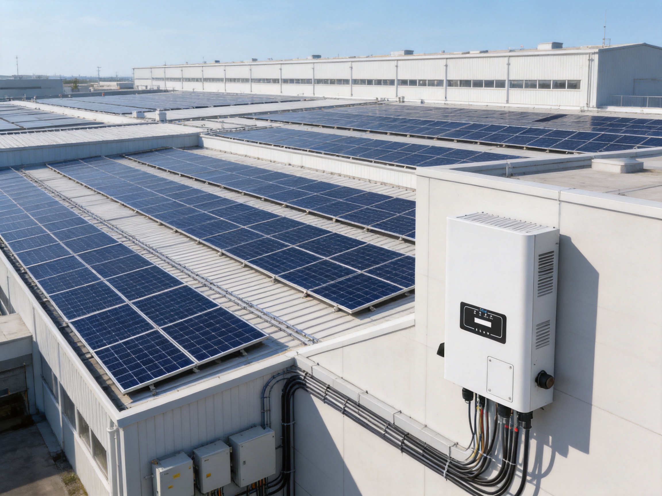
High Conversion Efficiency and Energy Yield
The series offers a maximum efficiency of up to 98.5%, with individual model values ranging from 98.1% to 98.5%. Euro efficiency values range from 97.5% to 98.0%, depending on the rated power model. These figures indicate that the inverter is designed to maintain low conversion losses across a realistic range of operating conditions rather than only at one ideal laboratory point.
Efficiency is important because every percentage point of conversion loss represents energy that is not available to the building or grid. In a small system, the absolute difference may appear modest. Over the operating life of a commercial installation, however, small losses accumulate across thousands of operating hours. Higher conversion efficiency can improve annual energy yield, reduce internal heat generation, and support a smaller thermal management requirement.
The inverter also specifies MPPT efficiency above 99%. This reflects the effectiveness of the tracking algorithm in locating and maintaining the photovoltaic array’s maximum power point. Conversion efficiency and MPPT efficiency are different measurements. MPPT efficiency concerns how effectively the inverter extracts available power from the array, while conversion efficiency concerns how efficiently the extracted DC power is converted into AC power.
The combination of high MPPT efficiency and high conversion efficiency is important in systems that experience rapidly changing irradiance. Passing clouds, morning and afternoon transitions, partial shading, and changing module temperature can all move the array’s optimum operating point. A responsive tracking system can help the inverter follow these changes and recover available energy more effectively.
DC oversizing capability
The photovoltaic input power range extends from 4.5 kW on the 3 kW model to 22.5 kW on the 15 kW model. This corresponds to a DC-to-AC design ratio of up to approximately 1.5 in the listed model range. Appropriate DC oversizing can improve inverter utilization during mornings, afternoons, winter conditions, and periods of low irradiance, when the array may not reach its nominal peak power.
DC oversizing must always be designed within the voltage, current, power, and local regulatory limits specified for the selected model. String voltage must remain below the maximum PV input voltage under the coldest expected module temperature. Operating voltage must remain inside the MPPT range, and the combined short-circuit current must remain within the inverter’s input limits. When these conditions are correctly observed, DC oversizing can improve the utilization of the AC conversion equipment.
Wide PV Voltage Range and Simplified System Design
The series has a maximum PV input voltage of 1100 V, a start-up voltage of 140 V, and an MPPT voltage range of 120 V to 1000 V. This broad operating range gives system designers room to configure strings for different module power ratings and local climate conditions.
The low start-up voltage can help the inverter begin operation earlier in the day when the array voltage is still building. The wide MPPT range also supports longer strings where appropriate, which may reduce DC cable current and voltage drop. At the same time, installers must carefully calculate the number of modules per string because the open-circuit voltage rises as module temperature falls.
A properly planned string should achieve a useful operating voltage under ordinary conditions while staying within the inverter’s safe voltage limits during the coldest expected weather. In warmer conditions, the voltage decreases, so the designer must also confirm that the minimum operating voltage remains adequate for start-up and MPPT operation.
This voltage flexibility can be an advantage over narrower-range products. A narrow MPPT range may force installers into less convenient string lengths or require more complex array grouping. By supporting a broad range, the product can adapt to different module formats and roof dimensions without compromising the basic electrical architecture.
Three-Phase Grid Compatibility
Three-phase output is a natural fit for commercial and industrial buildings that distribute power across three phases. The inverter supports rated output voltages of 220/380 V and 230/400 V, with an output voltage tolerance range of 0.85 to 1.1 times the nominal value. The rated grid frequency can be 50 Hz or 60 Hz, with the corresponding operating ranges of 45–55 Hz and 55–65 Hz.
The rated AC output current varies by model. For example, the 3 kW model has a rated current of approximately 4.6 A or 4.4 A depending on the nominal voltage, while the 15 kW model reaches approximately 22.8 A or 21.8 A. Maximum AC output current values range from approximately 5 A or 4.8 A to 25 A or 24 A across the series.
These ratings help engineers select circuit breakers, cables, isolators, distribution equipment, and protection devices. All electrical components must be sized according to the applicable local standards, installation method, ambient temperature, cable length, and expected fault conditions.
Power factor and grid support
The power factor adjustment range extends from 0.8 leading to 0.8 lagging. This gives the system operator or installer a useful degree of reactive power control where permitted by the grid operator. Reactive power support may be required in certain commercial networks or grid-code applications, especially where the system is connected to a relatively weak local distribution network.
The inverter also supports voltage source generator, or VSG, applications according to the stated product features. VSG-related functions can be relevant when an inverter is integrated into more advanced energy systems that require improved grid interaction or coordinated control. The exact operating mode and approval requirements depend on the complete system architecture and local regulations.
Total current harmonic distortion is specified at less than 3%, and DC injection current is specified at less than 0.5% of rated current. Low harmonic distortion helps maintain power quality and reduces the risk of unwanted interference with other electrical equipment. Anti-islanding protection further supports safe grid operation by preventing continued energization of a disconnected utility section under applicable operating conditions.
Zero-Export Applications and Energy Management
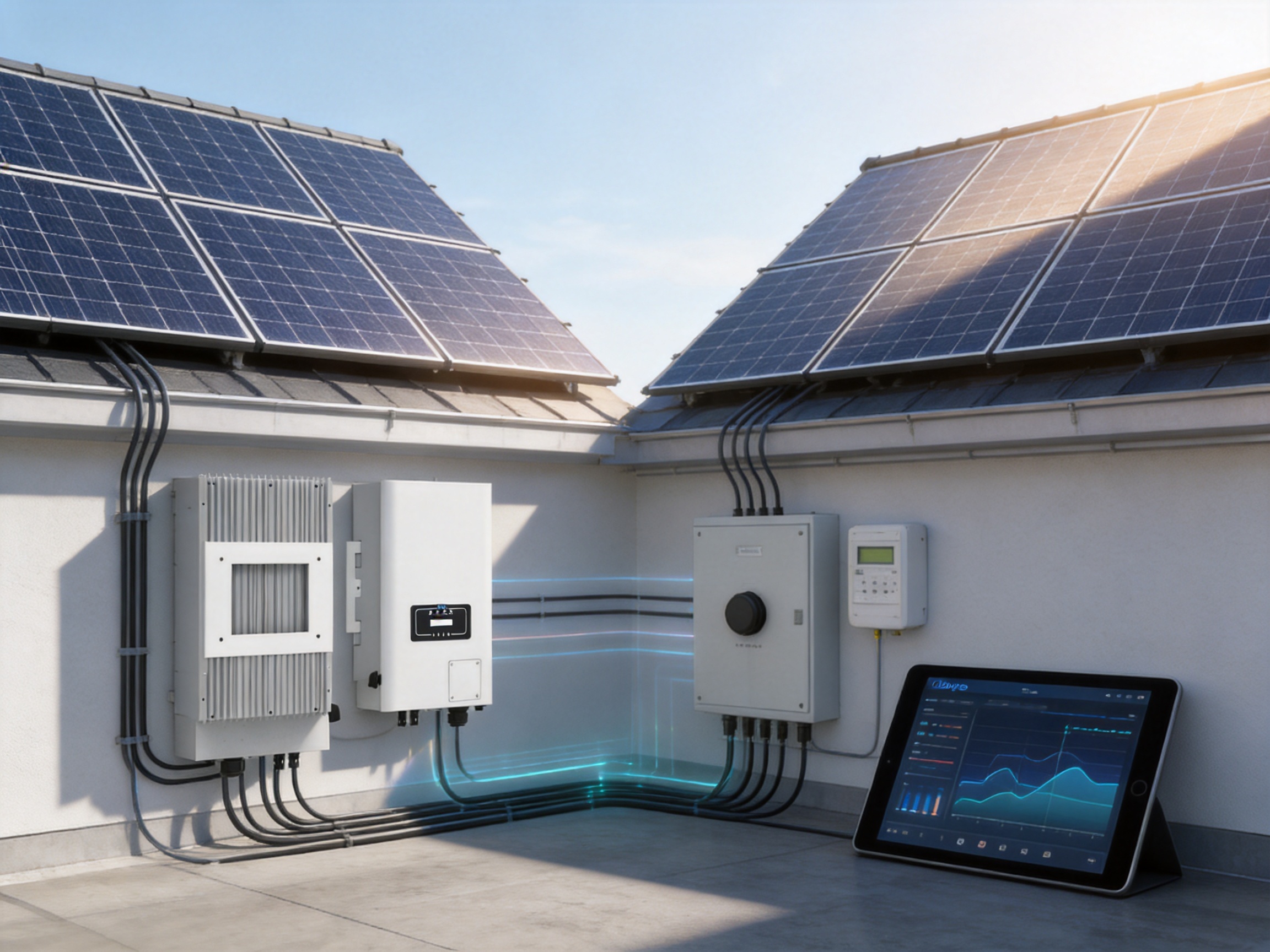
Many commercial users want to generate solar power without sending surplus electricity into the public grid. Reasons may include export restrictions, unfavorable feed-in tariffs, limited grid capacity, or a desire to maximize self-consumption. The series supports zero-export applications, making it suitable for sites where the photovoltaic system must match generation to local demand.
A zero-export system normally requires an appropriate energy meter or current transformer arrangement, a control device, and correct inverter settings. The system measures power flow at the point of common coupling and adjusts the inverter output so that surplus generation is reduced or redirected according to the configured limit.
Zero-export operation can be especially useful for factories, warehouses, cold-storage facilities, farms, and offices with significant daytime consumption. These sites often have loads that coincide with solar production, such as pumps, refrigeration systems, ventilation equipment, production machinery, and air-conditioning systems.
When designing a zero-export installation, engineers should evaluate the speed of load changes, meter placement, communication reliability, minimum inverter output, and the response time required by the local grid operator. The inverter’s control capabilities are valuable, but correct system integration remains essential for achieving reliable export limitation.
Protection Functions for Safer Operation
Photovoltaic systems operate outdoors and are exposed to electrical transients, moisture, temperature variation, lightning activity, and changing load conditions. The product includes a broad range of protective functions intended to improve system safety and help protect the inverter and connected equipment.
Listed protection functions include DC reverse polarity protection, AC output overcurrent protection, AC output overvoltage protection, AC output short-circuit protection, thermal protection, insulation impedance detection, DC component monitoring, anti-islanding protection, residual current detection, and surge protection. An integrated DC switch is also provided.
The surge protection level is specified as Type II on the DC side and Type II on the AC side. Surge protection should be coordinated with the building’s lightning protection system, external surge protective devices, grounding arrangement, and local installation standards. In areas with high lightning exposure, the complete installation may require additional protection beyond the inverter’s internal devices.
Optional AFCI function
An arc fault circuit interrupter is listed as optional. Arc faults can occur when electrical connections become loose, damaged, contaminated, or improperly assembled. An AFCI function can help detect characteristic electrical signatures associated with certain DC arc conditions and initiate a protective response.
Because AFCI availability may vary by model, market, or configuration, project planners should confirm the required option before ordering. Where local codes require arc fault protection, the installer should verify that the selected inverter configuration and complete system design satisfy those requirements.
Thermal and environmental protection
The inverter is designed for an operating temperature range of -25°C to +60°C, with derating above 45°C. This means the product can operate in cold and hot environments, while output capability may be reduced at higher temperatures to protect internal components and maintain reliable operation.
Natural cooling is used instead of a forced-air fan system. The absence of a cooling fan can reduce moving parts, fan noise, dust intake, and fan-maintenance requirements. It also contributes to the specified noise level of less than 45 dB. For installations near offices, homes, classrooms, or other occupied spaces, low operating noise can be a practical advantage.
The IP65 enclosure rating provides protection against dust ingress and water jets from different directions when the inverter is installed correctly. IP65 does not mean that the inverter should be placed underwater or exposed to uncontrolled flooding. Installation should follow the manufacturer’s clearances, cable-entry requirements, ventilation recommendations, and environmental limitations.
The permissible ambient humidity range is listed as 0% to 100%, and the permissible altitude is up to 4000 meters. At high altitude, air density is lower and thermal performance may be affected, so project designers should confirm whether any additional derating or special installation conditions apply.
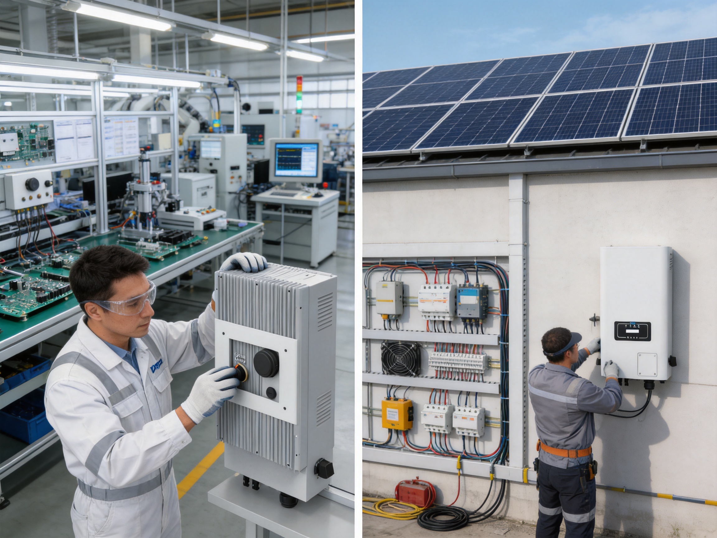
Monitoring and Communication
Modern photovoltaic systems require more than local operation. Owners, installers, and service teams need access to production data, alarms, operating status, and historical performance. The series provides RS485 and RS232 communication interfaces, while monitoring options include GPRS, Wi-Fi, Bluetooth, 4G, and LAN.
This communication flexibility allows the inverter to be adapted to different site conditions. Wi-Fi may be suitable for a small building with reliable network coverage. LAN can be preferred where a wired connection is available and stable communication is required. Cellular communication can support installations in rural or industrial areas where local internet service is limited. Bluetooth can simplify local commissioning and service access.
Optional intelligent string monitoring can improve visibility in larger or more complex arrays. String-level information may help identify abnormal current, shading, connector problems, fuse issues, or module degradation. Early detection can reduce the time required to locate a problem and help maintenance teams prioritize service work.
Monitoring is particularly valuable for commercial installations because performance losses can continue unnoticed if the system is inspected only occasionally. A monitoring platform can provide warnings when production falls below expected levels, when communication is interrupted, or when the inverter registers a protection event.
Data-driven maintenance
Reliable monitoring supports a shift from reactive maintenance to condition-based maintenance. Instead of waiting for a complete system failure, operators can review trends and investigate gradual changes. A small reduction in string current, for example, may indicate shading growth, soiling, a connector issue, or a module-level problem.
Monitoring data can also support warranty evaluation, energy forecasting, financial reporting, and comparison between similar arrays. For portfolio owners with multiple sites, standardized communication options make it easier to build consistent operating procedures across different locations.
Mechanical Design and Installation Practicality
The enclosure measures approximately 283 mm wide by 525 mm high. The listed depth is 178 mm for one equipment grouping and 188 mm for another, excluding connectors and brackets. Weight is approximately 11.5 kg or 12 kg depending on the model grouping.
This relatively compact and lightweight form factor can simplify wall mounting and reduce the labor required for handling. Installers can more easily position the equipment on suitable structural surfaces, provided that the wall, mounting hardware, and clearances are correctly selected.
Natural cooling also influences installation planning. Although the inverter does not rely on a fan, it still needs sufficient space around the enclosure to dissipate heat. Direct exposure to excessive solar heating should be minimized where possible. Cable bending radii, connector access, DC switch operation, and service clearance should be considered before final mounting.
The integrated DC switch can simplify local isolation during commissioning and maintenance. The switch does not replace all required AC isolation or external protection equipment, but it provides a convenient method for disconnecting the photovoltaic input at the inverter.
Comparison with Alternative Inverter Architectures
Product selection should be based on the requirements of the site rather than on a single headline specification. The three-phase string architecture offers a balanced solution between centralized conversion and distributed module-level electronics.
Compared with single-MPPT string inverters
A single-MPPT inverter can be economical for a simple, uniform array. However, it may be less flexible when strings face different directions or experience different shading conditions. The two-MPPT architecture of this series gives installers more freedom to separate array sections and improve energy tracking.
The additional tracker can reduce design compromises on roofs with multiple orientations. It also provides a practical way to group strings according to shading patterns without requiring a separate inverter for every roof section.
Compared with microinverter systems
Microinverters are installed at module level and can provide detailed module-level monitoring. They are often attractive for small roofs with severe shading or complex module layouts. However, a microinverter system places more electronic devices outdoors, increases the number of roof-level connections, and may involve higher equipment and installation costs for larger commercial arrays.
A three-phase string inverter can offer a simpler and more centralized architecture for medium-sized systems. It may reduce the number of conversion devices and make replacement or service more concentrated. The trade-off is that monitoring is typically organized around strings or inverter inputs rather than each individual module, unless additional optimizers or monitoring components are used.
Compared with single large central inverters
Central inverters can be efficient for utility-scale or very large homogeneous arrays, but they may be less flexible for smaller commercial sites with multiple roof sections. A string inverter approach distributes conversion across several units and can limit the impact of a single equipment outage.
The 3 kW to 15 kW range is well suited to distributed commercial generation, where roof geometry, construction phases, and electrical loads often vary from one building section to another. Multiple appropriately selected string inverters can be arranged to match the site’s expansion plan and electrical distribution design.
Compared with optimizer-based systems
Power optimizers can improve the performance of modules affected by uneven shading or mismatch. They may also provide detailed module-level data. However, they add components, installation steps, and compatibility considerations. The two-MPPT design of this series may address many ordinary roof-layout challenges without requiring an optimizer on every module.
Optimizers may still be beneficial in particularly complex arrays. The appropriate decision depends on shading severity, module arrangement, monitoring requirements, safety rules, and project economics. The strength of this inverter platform is that it provides substantial string-level flexibility as a standard design foundation.
Manufacturing Strengths and Quality-Oriented Production
The company behind the product is Ningbo Deye Inverter Technology Co., Ltd., a technology manufacturer with activities covering research and development, product design, production, sales, and service. Founded in 2000 and listed on the Shanghai Stock Exchange in April 2021, the company has developed a broad portfolio covering photovoltaic inverters, energy storage systems, microinverters, environmental appliances, and related energy technologies.
Its manufacturing strength is supported by vertical coordination across multiple stages of the product lifecycle. Combining research and development with production allows engineering teams to evaluate product design, component selection, firmware behavior, thermal performance, protection functions, and production requirements as an integrated process.
For an inverter manufacturer, this integrated structure is valuable because power electronics products must be designed for both electrical performance and repeatable manufacturing. A circuit that works in a laboratory prototype must also be assembled consistently, tested thoroughly, protected against environmental stress, and supported over many years in the field.
Research and development capabilities
The company’s product portfolio includes string inverters from 1 kW to 136 kW, energy storage inverters from 3 kW to 80 kW, and microinverters from 300 W to 2.2 kW. This range indicates experience across different power levels and application environments.
Developing products across these categories requires knowledge of high-frequency switching, DC and AC protection, digital control, maximum power point tracking, grid synchronization, communication systems, thermal design, battery integration, and regulatory compliance. The three-phase string inverter series benefits from this broader technical foundation.
The company also develops energy management and monitoring solutions, including the Deye Cloud App and LoRa-based wireless energy management technologies. These capabilities support a more complete approach to solar system operation, connecting the inverter to monitoring, control, and energy optimization functions rather than treating the inverter as an isolated conversion device.
Production consistency
Consistent production is essential for products installed in large numbers across different climates and grid environments. Manufacturing controls should include incoming material inspection, automated or controlled assembly processes, soldering quality management, torque verification, insulation testing, functional testing, calibration, firmware control, and final inspection.
While the exact internal factory process for each production line is not detailed in the supplied material, the company’s integrated manufacturing model provides a foundation for coordinated quality control. A mature inverter production operation typically uses traceability systems so that key components, production batches, test results, and firmware versions can be associated with individual units.
Such traceability helps manufacturers investigate field issues, manage corrective actions, and maintain consistent product performance. It also supports after-sales service by giving technical teams a clearer record of the equipment’s production and test history.
Testing and compliance orientation
The series is associated with a broad set of grid, safety, and electromagnetic compatibility standards. Listed grid regulations include IEC 61727, IEC 62116, CEI 0-21, EN 50549, NRS 097, RD 140, UNE 217002, OVE-Richtlinie R25, G98, G99, and VDE-AR-N 4105.
Safety and electromagnetic compatibility references include IEC/EN 61000-6-1, IEC/EN 61000-6-2, IEC/EN 61000-6-3, IEC/EN 61000-6-4, IEC/EN 62109-1, and IEC/EN 62109-2. Additional certificates are listed for standards and national requirements in areas including Germany, France, Spain, and other markets.
Compliance documentation does not eliminate the need for local approval, but it gives distributors, installers, and project developers a stronger technical basis for market entry and system certification. It also demonstrates that the inverter has been developed with international operating conditions and regulatory expectations in mind.
Installation Design Considerations
Although the inverter is designed for practical installation, system performance depends on correct engineering and workmanship. Before installation, the designer should confirm the selected model, module electrical characteristics, string length, maximum cold-weather voltage, maximum operating current, short-circuit current, DC-to-AC ratio, and expected temperature range.
The AC side should be designed with suitable overcurrent protection, isolation, surge protection, grounding, and cable sizing. The installer should also verify phase sequence, neutral connection, protective earth, grid voltage, frequency, and local utility requirements.
PV connectors should be compatible, fully engaged, correctly crimped, and protected from water accumulation. Poorly assembled connectors are a common source of resistance, heating, and arc risk. Cable routes should prevent mechanical damage and avoid unnecessary exposure to standing water or sharp edges.
The inverter should be mounted on a structurally suitable surface in a location that provides adequate heat dissipation, service access, and protection from avoidable environmental hazards. Even with IP65 protection, the unit should not be installed where it may be subjected to persistent flooding, corrosive chemicals, or uncontrolled condensation.
Commissioning and verification
Commissioning should include visual inspection, polarity verification, insulation testing, grounding checks, AC voltage confirmation, communication setup, parameter configuration, and functional verification of protective devices. The installer should confirm that the inverter recognizes the expected PV input voltage and that each MPPT receives the correct string group.
Monitoring should be configured before handover. The owner should receive information about normal operating indicators, alarm interpretation, shutdown procedures, maintenance intervals, and contact channels for technical support.
Where zero-export operation is used, the meter or current transformer must be installed in the correct location and oriented correctly. The system should be tested under changing load conditions to confirm that export control responds as intended.
Service Life, Warranty, and After-Sales Support
The product carries a listed five-year warranty. Warranty terms normally depend on the sales region, installation conditions, commissioning requirements, and documentation. Buyers should confirm the precise warranty scope and any available extension options before purchase.
Long-term inverter value depends on more than initial efficiency. Serviceability, availability of spare parts, software support, monitoring access, technical documentation, and responsive troubleshooting all influence the lifetime cost of ownership.
The company maintains international sales and service capabilities, with products reported as being sold in more than 140 countries and regions. A broad installed base can support a larger network of installers, distributors, and technical partners. However, the quality of local service still depends on the specific market and supply chain, so project owners should verify local support arrangements before committing to a large deployment.
Remote monitoring can reduce unnecessary site visits by allowing service teams to review alarms and operating conditions in advance. When a visit is required, stored operating data can help technicians arrive with the correct tools and replacement components.
Benefits for Different User Groups
For installers
Installers benefit from a consistent product family covering 3 kW to 15 kW, two MPPTs, a broad voltage range, integrated protection, natural cooling, and multiple communication options. These features can reduce the need to learn entirely different platforms for every project size.
The compact enclosure and moderate weight can simplify transport and mounting. The integrated DC switch and optional monitoring functions also support a more organized commissioning process.
For commercial building owners
Building owners receive a solution designed for three-phase electrical networks, high self-consumption, zero-export control, and remote performance monitoring. The range of power classes makes it easier to select equipment that matches the building’s load and roof capacity.
High efficiency can support better energy yield, while low harmonic distortion and adjustable power factor can contribute to grid-friendly operation. The five-year warranty provides a defined initial protection period for the investment.
For system designers
Design engineers can use the two MPPTs to accommodate mixed roof orientations and the wide voltage range to optimize string configuration. The 1100 V maximum input voltage and model-specific current capability provide a useful basis for modern high-power module selection.
The availability of multiple grid certificates and national compliance references can also simplify early-stage product qualification. Final approvals remain the responsibility of the project team and local authorities, but existing documentation can reduce duplicated assessment work.
For distributors and energy solution providers
Distributors can offer a scalable product family that fits small commercial systems through medium-sized installations. The broader company portfolio also creates opportunities to combine string inverters with energy storage, microinverters, monitoring, EV charging, and energy management products when the project requires a more complete solution.
Recommended Selection Process
The correct model should be selected through a structured engineering process. First, determine the required AC output based on the building load, available grid connection, export policy, and expected annual solar production.
Second, calculate the appropriate PV array size. The planned DC input should remain within the selected model’s maximum PV input power. Designers should consider whether a modest DC oversizing ratio will improve production during low-irradiance periods without causing excessive clipping.
Third, design the strings according to module voltage and current. The cold-weather open-circuit voltage must remain below 1100 V. The normal operating voltage must fall within the 120–1000 V MPPT range, and the array must reach at least the required start-up voltage. Operating and short-circuit current limits must also be respected.
Fourth, evaluate roof orientation and shading. Different roof planes should generally be separated between the two trackers when their electrical behavior differs significantly. If shading is severe or highly irregular, the design team should assess whether optimizers or microinverters would provide additional value.
Fifth, confirm the grid code, communication method, export-control requirement, enclosure location, ambient temperature, altitude, and service access. Finally, verify the availability of the selected options, including AFCI, monitoring hardware, and any required accessories.
Q&A
What is the power range of this inverter series?
The series covers rated AC output powers from 3 kW to 15 kW. Available models are 3 kW, 4 kW, 5 kW, 6 kW, 7 kW, 8 kW, 9 kW, 10 kW, 12 kW, and 15 kW.
Is the inverter suitable for three-phase buildings?
Yes. It is a three-phase string inverter using a 3L/N/PE grid connection. It supports nominal output systems of 220/380 V and 230/400 V, subject to local grid requirements and approval.
How many MPPTs does each inverter have?
Each model has two maximum power point trackers. Depending on the model group, the string configuration is listed as either two trackers with one string per tracker or two trackers with one or two strings per tracker.
What is the maximum photovoltaic input voltage?
The maximum PV input voltage is 1100 V. String voltage must be calculated under the coldest expected conditions to ensure that the open-circuit voltage remains within this limit.
What is the MPPT operating voltage range?
The MPPT voltage range is 120 V to 1000 V, and the start-up voltage is 140 V. The string design should remain within the relevant limits across the expected operating temperature range.
What is the highest stated efficiency?
The highest stated maximum efficiency is 98.5%. Individual models have maximum efficiency values between 98.1% and 98.5%, while Euro efficiency values range from 97.5% to 98.0%.
Can the inverter work in a zero-export system?
Yes. Zero-export application is listed as a product feature. A complete zero-export installation requires compatible metering or current-transformer equipment, correct control settings, and suitable commissioning.
Does it support remote monitoring?
Yes. Communication interfaces include RS485 and RS232. Optional monitoring methods include GPRS, Wi-Fi, Bluetooth, 4G, and LAN. Intelligent string monitoring is also listed as an optional function.
What protection functions are included?
Listed protections include DC reverse polarity, AC overcurrent, AC overvoltage, AC short circuit, thermal protection, insulation impedance detection, DC component monitoring, anti-islanding, residual current detection, and Type II surge protection on both the DC and AC sides. AFCI is optional.
Can it operate in hot and cold climates?
The listed operating temperature range is -25°C to +60°C, with derating above 45°C. The inverter should be installed in a location that allows heat dissipation and complies with the manufacturer’s installation requirements.
Does the inverter use a cooling fan?
No. The product uses natural cooling. This can reduce fan-related maintenance, dust intake, moving parts, and operating noise. Adequate installation clearance is still required.
What is the enclosure protection rating?
The enclosure is rated IP65. This provides protection against dust and water jets under specified test conditions, but it does not permit submersion or installation in areas exposed to uncontrolled flooding.
What is the warranty period?
The listed warranty period is five years. Buyers should confirm the exact warranty terms, regional conditions, and any available extensions with the supplier or authorized distributor.
Who manufactures the product?
The product is manufactured by Ningbo Deye Inverter Technology Co., Ltd., a technology company involved in photovoltaic inverters, energy storage systems, microinverters, energy management, and related products.
What makes the product competitive?
Its principal competitive strengths include two MPPTs, high conversion efficiency, a wide PV voltage range, support for zero-export applications, broad communication options, integrated protection, natural cooling, a compact enclosure, a 3 kW to 15 kW product range, and documentation for multiple international grid and safety standards.
Conclusion
The SUN-(3-15)K-G06P3-EU-BM2-P1 series is designed as a flexible and efficient three-phase string inverter platform for commercial, agricultural, light-industrial, and larger residential photovoltaic systems. Its two-MPPT architecture provides greater freedom for mixed roof orientations and different shading conditions, while the wide voltage range supports practical string design with modern photovoltaic modules.
Maximum efficiency of up to 98.5%, MPPT efficiency above 99%, low harmonic distortion, adjustable power factor, and three-phase grid compatibility give the series a strong technical foundation. Zero-export capability and multiple communication options extend its usefulness in self-consumption projects, monitored commercial systems, and energy management applications.
Protection functions, IP65 construction, natural cooling, a -25°C to +60°C operating range, and optional intelligent string monitoring further support reliable outdoor operation. Compared with single-MPPT products, the series offers greater design flexibility. Compared with microinverter or optimizer-based systems, it can provide a more centralized and potentially simpler architecture for medium-sized arrays. Compared with larger central inverters, its distributed string format is better suited to many commercial rooftops with varied orientations and staged development.
The manufacturer’s experience in photovoltaic inverters, energy storage, microinverters, monitoring, and energy management strengthens the product’s position as part of a broader solar technology portfolio. Its international certifications, integrated research and manufacturing capabilities, and global market presence provide additional support for installers, distributors, and project developers.
As with any grid-connected power conversion product, final performance depends on correct model selection, string design, installation workmanship, protection coordination, commissioning, and compliance with local regulations. When these factors are properly managed, the series offers a balanced combination of efficiency, flexibility, safety, monitoring, and long-term practicality for modern three-phase solar installations.
References
1. Product technical data for the SUN-(3-15)K-G06P3-EU-BM2-P1 three-phase string inverter series.
2. Manufacturer product information covering PV input characteristics, AC output ratings, protection functions, communication options, and environmental specifications.
3. IEC 62109-1 and IEC 62109-2, Safety of Power Converters for Use in Photovoltaic Power Systems.
4. IEC 61727, Photovoltaic Systems: Characteristics of the Utility Interface.
5. IEC 62116, Utility-Interconnected Photovoltaic Inverters: Test Procedure of Islanding Prevention Measures.
6. EN 50549, Requirements for Generating Plants to Be Connected in Parallel with Distribution Networks.
7. IEC 61000 series, Electromagnetic Compatibility Requirements for Electrical and Electronic Equipment.
8. General photovoltaic system design principles for maximum voltage, operating current, short-circuit current, string sizing, and DC-to-AC ratio selection.
9. Manufacturer company information regarding research and development, manufacturing, photovoltaic products, energy storage systems, monitoring platforms, and international market activities.
Product: SUN-3/4/5/6/7/8/9/10/12/15K-G06P3-EU-BM2-P1

PREV:No previous article
NEXT:Three-Phase High-Voltage Hybrid Inverter for Flexible Solar Energy Management
Share
Product recommendations
news recommendations
-
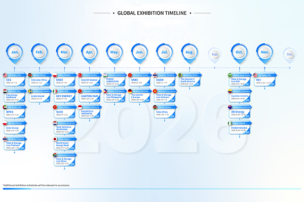 GLOBAL EXHIBITION TIMELINE
*Click to view larger image
-
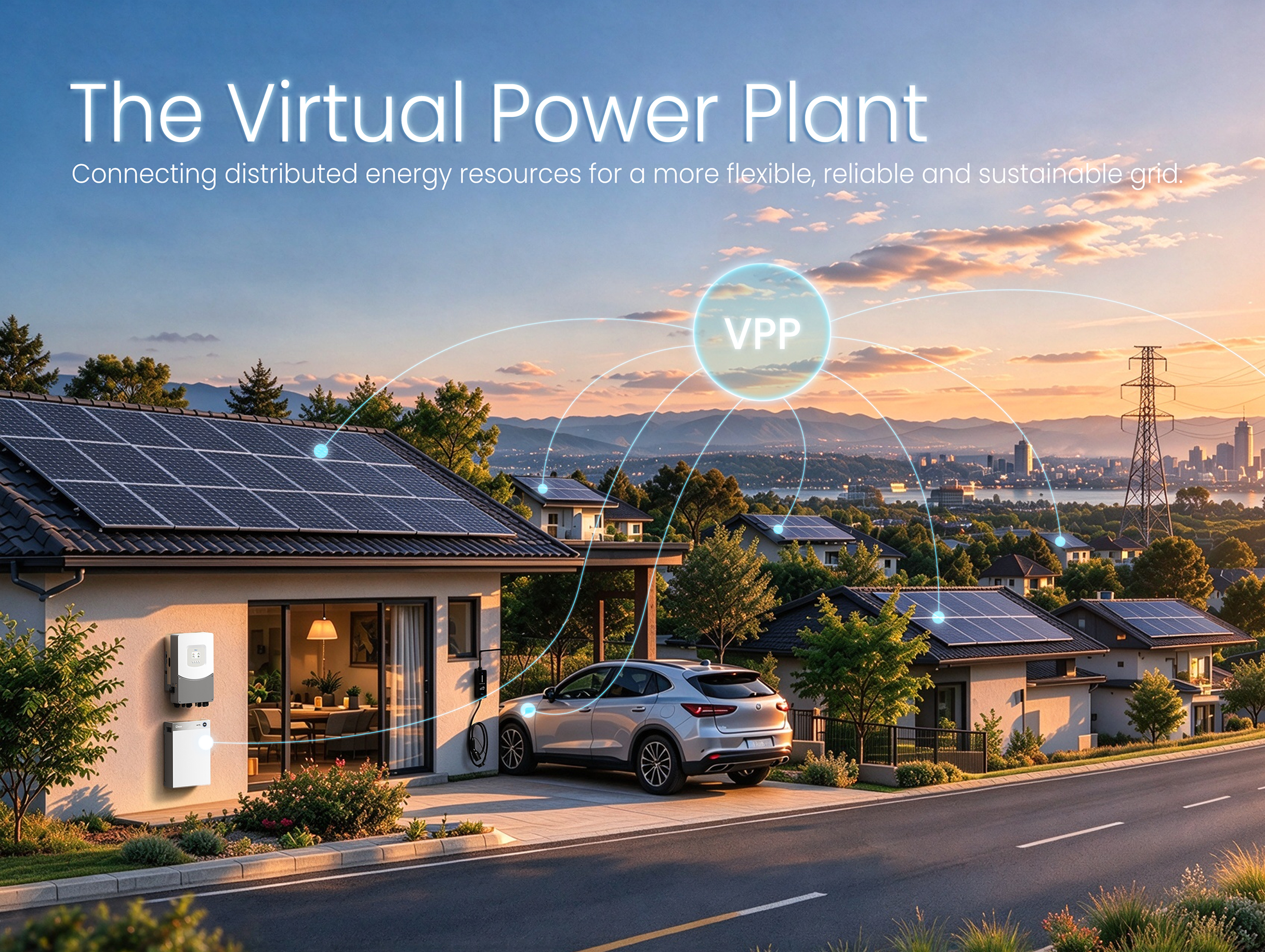 From Centralized Grids to Virtual Power Plants: The Next Evolution of the Power System
For more than a century, power systems around the world have relied on a centralized model. Large p...
-
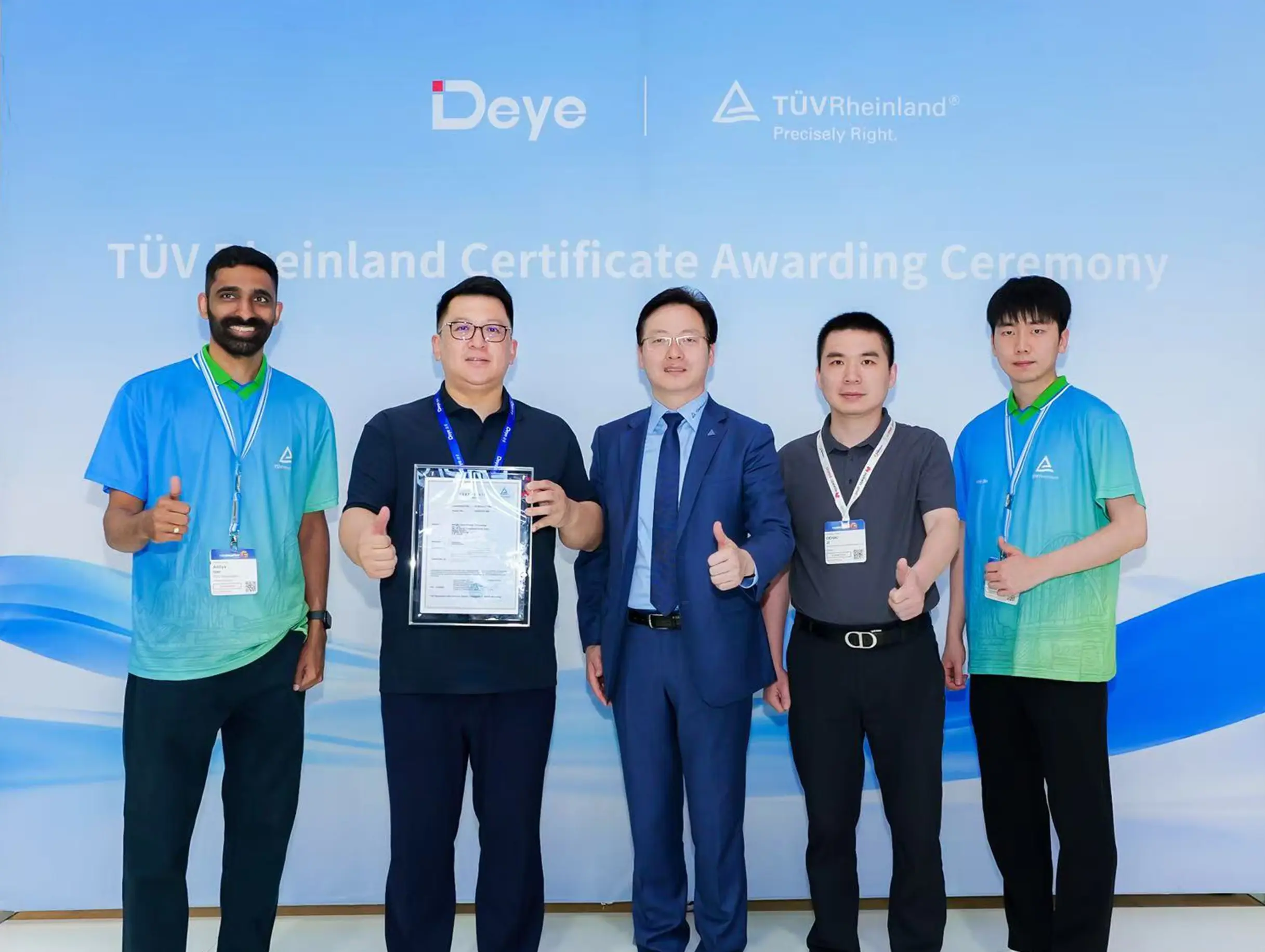 Deye Secures Multiple TÜV Rheinland Certifications at The smarter E Europe
On June 23, the opening day of The smarter E Europe 2026, Deye was officially awarded several presti...

Copyright@ 2024.Ningbo Deye Inverter Technology Co.,Ltd. All rights reserved. Solar Inverter Manufacturer
